
Aerospace Applications
Aerospace Laser Marking Applications
Aerospace laser marking is not selected by laser power alone. Start with the actual workpiece, material and surface condition, mark content, permitted material effect, geometry, inspection method and production volume. Then use representative samples to determine the laser route, fixture, optics, verification and final machine configuration.
Begin an Engineering ReviewExplore Aerospace Applications
- Part and serial identification
- Small Data Matrix codes
- Material and surface limits
- Sample-led configuration
Workpiece & Application Scope
Which Aerospace Parts and Marking Tasks Fit This Application?
This page is for aerospace component manufacturers, suppliers, assembly teams and maintenance-related applications that need permanent or machine-readable identification on real parts. The first step is to identify the workpiece and marking task before discussing equipment.
Aerospace Components
Machined brackets, housings, plates, fittings, structural parts and other components that require part numbers, serials, lot information or controlled identification.
Explore component markingTurbine & Engine Components
Engine-related metal parts such as blades, vanes, rings, housings and other high-value components where alloy condition, heat history, mark depth and critical surfaces require tighter review.
Explore engine componentsCables & Connectors
Wire jackets, cable assemblies, heat-shrink identification sleeves, connector housings and similar interconnect parts where polymer type, colour, curvature and handling affect readability.
Explore cable and connector markingAerospace Data Matrix
Small direct-part marks and compact machine-readable codes where cell size, glare, surface finish, curvature, focus and verification conditions must be controlled together.
Explore Data Matrix markingStart with the actual part, not the industry label. “Aerospace” does not determine the laser. A titanium bracket, anodized aluminum housing, coated connector and polymer cable jacket can require very different marking mechanisms and acceptance methods.
Why Mark
Why Are Aerospace Components Marked?
The reason for marking is usually identification and traceability throughout manufacturing, inspection, assembly, service or maintenance. The required content and evidence depend on the controlling drawing, customer specification and actual production process.
- Unique component identityLink a physical part to its part number, serial number, configuration or revision.
- Lot and process traceabilityAssociate production units with batch, material, process or inspection records.
- Assembly controlReduce the risk of mixing similar parts, revisions or configurations during production and service.
- Machine-readable lifecycle dataUse compact codes where scanners or verification systems need to retrieve controlled information.
- Maintenance and service identificationKeep an identifier available through handling, cleaning and other project-defined exposure conditions.
- Inspection and record linkageConnect the physical mark to the required inspection, traveller, build or service record.
What Is Usually Marked?
| Mark content | Typical purpose | What must be defined before testing |
|---|---|---|
| Part number / serial number | Unique or controlled component identity | Character height, marking zone, orientation, permanence and permitted surface effect. |
| Lot / batch / revision | Production and configuration traceability | Data source, update rules, record linkage and inspection method. |
| Data Matrix / small DPM code | Compact machine-readable identification | Code size, cell size, contrast, surface condition, reader/verifier, lighting and acceptance method. |
| Logo / supplier / specification text | Visual supplier or configuration identification | Permitted zone, minimum feature size, visual consistency and drawing restrictions. |
Result Variables
What Determines the Aerospace Laser Marking Result?
A material name is only one input. The usable process window comes from the interaction between the substrate, surface condition, permitted material effect, mark geometry, positioning, inspection method and production requirement.
| Variable | Why it matters | What to define |
|---|---|---|
| Base material / alloy | Changes absorption, thermal response and the marking mechanism available. | Exact grade or material family where known. |
| Heat treatment / coating / anodizing / plating | The top layer may respond differently from the base material and may need to be preserved, modified or selectively removed. | Actual treatment or layer stack and whether base exposure is allowed. |
| Surface finish | Polished, machined, blasted or coated surfaces can change contrast, glare and code verification stability. | Representative production finish, not only a generic coupon. |
| Permitted material effect | Some parts allow a visible surface change but restrict depth, heat input or removal of protective layers. | Drawing-defined or project-defined prohibited and acceptable effects. |
| Mark content and feature size | Fine text and small code cells change optical, focus and verification requirements. | Character height, line width, code size, cell size and orientation. |
| Geometry and height variation | Curvature, tilt and changing Z-height can move the surface out of the useful focal range or distort a code. | Marking zone size, curvature, height range and part orientation. |
| Positioning and datum | Part-to-part location variation can become a mark-placement or verification problem. | Datum, fixture repeatability, allowable position tolerance and whether vision is required. |
| Inspection / verification | A visually dark mark is not automatically an acceptable machine-readable mark. | Human inspection, scanner, verifier, lighting, record method and project acceptance criteria. |
| Production volume / duty cycle | The laser process may be fast while loading, locating, data handling or verification limits total takt time. | Parts per hour/shift, loading method, changeover, verification and reject handling. |
Target Result
What Should an Acceptable Aerospace Mark Achieve?
Define acceptance before tuning parameters. A useful target describes not only how the mark looks, but also what it must preserve, how it will be inspected and whether the process can repeat in production.
- Correct contentThe required serial, part number, lot, revision or encoded data is correct and traceable.
- Correct locationThe mark stays within the permitted zone and respects datum, orientation and protected areas.
- Readable resultText or symbols remain legible under the intended inspection conditions.
- Stable machine-readable codeData Matrix or other DPM content meets the project-defined reader or verification method, not merely a one-time scan.
- Permitted surface effectDepth, heat effect, coating change or material removal remains within the actual drawing or process limits.
- Required durabilityThe mark remains acceptable after the cleaning, handling, thermal, corrosion or other exposure checks required by the project.
- Repeatable placement and appearanceMultiple representative parts remain within the same acceptance window.
- Production-ready cycleLoading, marking, verification, data handling and reject control can meet the required throughput.
Geometry, Positioning & Handling
How Do Part Shape and Loading Affect the Marking Process?
The same material can require a different machine layout when the mark moves from a flat coupon to a curved, height-varying or difficult-to-locate production part.
| Part condition | What can go wrong | Configuration direction to evaluate |
|---|---|---|
| Flat, repeatably located surface | Usually the simplest case, but placement still depends on datum and fixture repeatability. | Stable fixture and standard workstation. |
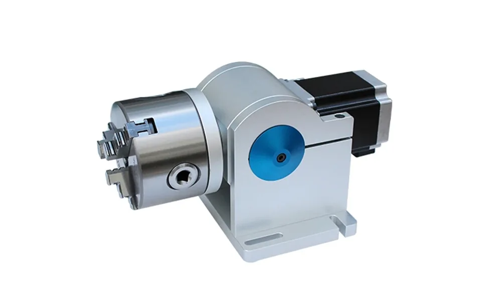
| Cylindrical or circumferential surface | Focus and code geometry change as the surface rotates away from the marking plane. | Rotary cylindrical marking or a controlled indexed fixture. |
| Curved or height-varying surface | Different areas can leave the useful focal range or create inconsistent feature geometry. | 3D curved-surface evaluation or controlled Z positioning. |
| Variable placement between parts | Good parameters still fail if the mark lands outside the allowed zone. | Vision positioning or improved mechanical datum control. |
| Large or awkward aerospace component | The marking head, enclosure or part may not fit a standard bench layout. | Review head orientation, working envelope, access and fixture concept before machine selection. |
| Takt-controlled or integrated flow | Part arrival, data trigger and verification can become the cycle bottleneck. | Online/flying evaluation only when the real line motion and trigger conditions support it. |
First-Test Laser Route
Which Laser Route Should Be Tested First?
Treat this as a starting route for sample testing, not a final machine recommendation. The actual laser, optics and parameters must be confirmed on the real material, surface and marking zone.
| Workpiece condition | First route to evaluate | Why start there | What still needs confirmation |
|---|---|---|---|
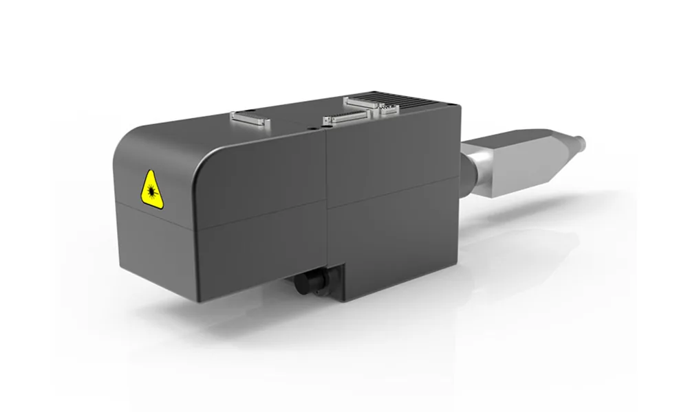
| Bare or treated metal component | Fiber laser; include MOPA evaluation where pulse-width control may help the target surface response. | A practical starting family for many metal identification tasks. | Alloy, treatment, finish, permitted depth/heat effect, contrast target and cycle time. |
| Anodized, plated or coated metal | First determine whether the top layer must be preserved, modified or selectively removed, then test the suitable fiber/MOPA route. | The surface layer can control the marking mechanism more strongly than the base metal name. | Layer construction, base exposure, edge quality, adhesion and required durability. |
| Polymer cable jacket or connector housing | UV or fiber-family testing based on the actual resin, colour, additives and permitted thermal effect. | Polymer response varies strongly with formulation and pigmentation. | Exact material, contrast mechanism, surface damage, handling durability and mark speed. |
| Small Data Matrix / fine DPM | Choose the laser family from the material first, then optimize optics, focus, fixture and verification as one system. | Code quality is not controlled by laser type alone. | Cell size, marking zone, glare, curvature, lighting, verifier and repeatability. |
| Curved or height-varying part | Test the material route together with rotary, Z-control or 3D focus strategy as required. | A flat coupon can hide real focus and geometry problems. | Actual surface profile, orientation, fixture repeatability and full code/text geometry. |
Do not copy a parameter set from another aerospace part simply because the alloy name looks similar. Surface finish, treatment, coating, geometry, focal condition and acceptance criteria can move the usable process window.
Failure Diagnosis
Common Aerospace Laser Marking Failure Modes
A failed mark is more useful when the visible symptom points to the next check. Diagnose the part, surface, focus, fixture, code geometry and production conditions before simply increasing power.
| Observed problem | Likely variables to inspect first | How to confirm the cause |
|---|---|---|
| Dark mark, but excessive surface change | Fluence, pulse behaviour, number of passes, overlap, focus and permitted material effect. | Compare the same part condition at reduced energy input and inspect the surface against the drawing-defined limit. |
| Weak or inconsistent contrast | Surface finish, coating/treatment variation, focus, contamination and process window. | Hold geometry constant and compare representative surfaces from the real production condition. |
| Data Matrix scans once but verifies inconsistently | Cell geometry, glare, lighting, contrast uniformity, surface finish, curvature and verifier setup. | Repeat verification under the defined inspection condition across multiple representative parts. |
| One side is sharp and the other is blurred | Part tilt, height variation, focal plane and fixture seating. | Measure or control Z variation, then repeat the mark without changing unrelated parameters. |
| Code or text becomes distorted on a curved part | Curvature, field distortion, part orientation and motion strategy. | Compare against a flat reference, then test rotary or 3D compensation on the actual geometry. |
| Mark position drifts between parts | Datum, fixture repeatability, operator loading and part tolerance. | Separate laser repeatability from workpiece-location variation using a controlled fixture or vision check. |
| Coating edge chars, flakes or exposes too much base material | Layer response, energy concentration, overlap and whether the process should preserve or remove the layer. | Test the actual coating stack at controlled energy levels and inspect the transition zone. |
| Samples pass, but production is inconsistent | Material lot, finish variation, fixture, focus, recipe control, lens contamination and operator handling. | Compare failed and accepted parts with recorded material, fixture, focus and recipe conditions. |
| Laser mark is fast, but the station misses takt time | Loading, locating, data transfer, verification, reject handling and changeover. | Time the full cycle instead of using scanner marking time as the production rate. |
Production Workflow
How Does an Aerospace Marking Process Move Into Production?
A production-ready solution must control the whole path from the incoming part to the final inspection record. Marking speed by itself is not the line cycle.
- Load and identify the workpieceConfirm the correct part, orientation, production state and applicable recipe before marking.
- Locate the datum and marking zoneUse a repeatable fixture, controlled stop, vision or another positioning method appropriate to the actual tolerance.
- Load the correct mark dataControl serial, part number, lot, revision or encoded data so the mark matches the intended production record.
- Mark with the approved process windowUse the validated laser route, optics, focus and recipe without transferring uncontrolled parameters from another part.
- Inspect or verifyApply the project-defined human inspection, scanner or verifier condition and record the result where required.
- Handle rejects and recordsDefine what happens when content, position, code quality or surface condition fails acceptance, and keep the required traceability record.
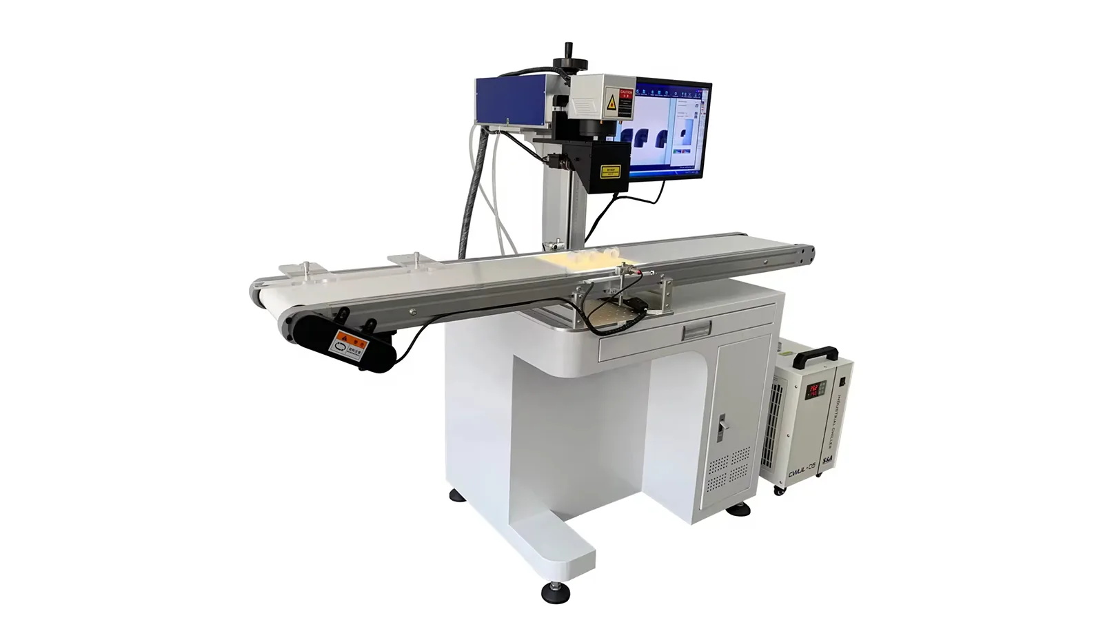
Measure the full cycle: loading + locating + data handling + marking + verification + reject handling + record update. This is the cycle that should drive production configuration and capacity decisions.
Sample Acceptance
How Should Representative Aerospace Samples Be Accepted?
Use representative production parts, the real surface condition and the controlling drawing or project requirements. The goal is not to produce one attractive sample; it is to prove that the proposed process has a usable and repeatable acceptance window.
| Acceptance item | What to verify | Pass basis |
|---|---|---|
| Part and material identity | Correct material, grade/treatment, coating, surface finish and production state. | Matches the representative production condition supplied for the test. |
| Mark content | Correct text, serial, lot, revision, code content and orientation. | Matches the drawing, data source or approved sample definition. |
| Mark location | Placement relative to datum, protected surfaces and the permitted marking zone. | Within the project-defined location tolerance. |
| Visual quality | Legibility, edge quality, consistency and any required contrast target. | Against the defined inspection condition, not subjective appearance alone. |
| Machine-readable quality | Reader/verifier result, lighting condition, code geometry and repeatability where DPM is required. | Against the project-specified verification method and acceptance level. |
| Material / surface integrity | Depth, heat effect, coating damage, cracking, excessive removal or other prohibited effects. | Within the actual drawing, process or engineering acceptance boundary. |
| Durability | Cleaning, handling, thermal, corrosion or other post-mark exposure required by the project. | Mark remains acceptable after the specified test condition. |
| Repeatability | Multiple parts across representative surface or material variation. | The same approved window continues to meet the acceptance criteria. |
| Full-cycle takt | Load, locate, mark, verify, reject and record handling. | Meets the real production target rather than scanner-only marking time. |
Sample evidence supports process evaluation; it does not by itself establish aerospace qualification. Final acceptance must follow the controlling drawing, customer specification and any required engineering, quality or customer approval process.
From Test Result to Machine
How Do Sample-Test Results Determine the Final Machine Configuration?
The final machine should reflect what the sample and production tests actually reveal. Laser source, optics, motion, fixture, vision, verification, extraction and automation are configuration consequences of the workpiece and acceptance result—not assumptions made before testing.
| What the test reveals | What it can change in the final configuration | Why |
|---|---|---|
| A metal surface reaches the target result only within a narrow pulse/energy window. | Fiber-family source selection, including MOPA where appropriate, pulse control and recipe management. | The source must support the validated metal-marking process window rather than a generic setup. |
| The polymer or coated surface is heat-sensitive. | UV or other suitable source evaluation, different optics and tighter energy control. | Reducing unwanted thermal or layer damage may be more important than raw marking speed. |
| Very small text or DPM cells are required. | Field size, lens/optical configuration, focus control, fixture accuracy and verification system. | Feature size and code quality set resolution and positioning demands. |
| The mark is on a cylinder or around a circumference. | Rotary axis, indexed motion, compatible fixture and software path. | The marking plane changes as the part rotates. |
| The marking zone has significant curvature or height variation. | 3D/dynamic focus, controlled Z motion or a fixture that reduces height variation. | Keeping the surface within the validated focal condition becomes part of the process. |
| Part position varies between cycles. | Vision positioning, datum detection or a more repeatable fixture. | Good marking parameters cannot compensate for uncontrolled part location. |
| DPM verification is required after every mark. | Camera/verifier, controlled illumination, software integration and result logging. | Verification becomes a production step, not a separate manual check. |
| Serial data must come from PLC, MES or another controlled source. | Data interface, scanner/PLC/MES integration, recipe and record logic. | The physical mark must remain linked to the correct digital record. |
| Manual loading cannot meet repeatability or takt time. | Improved fixture, assisted loading, indexing, automation or integrated motion. | The bottleneck is handling rather than laser exposure time. |
| Smoke, residue or process debris affects optics or inspection. | Local extraction and airflow configuration sized to the actual marking process. | Process stability includes keeping the marking and inspection area controlled. |
| The part is large, heavy or difficult to access. | Working envelope, enclosure layout, head orientation, XYZ motion or project-specific fixture architecture. | The physical workpiece may drive machine layout more strongly than the laser source. |
For system-level requirements such as PLC/MES connection, scanner workflows and production data handling, see Traceability Data Integration. For material-specific behaviour, use the relevant material page together with representative sample testing.
Next Steps
Turn the Aerospace Marking Requirement Into a Test Plan
Send the actual workpiece information, material and surface condition, required mark, target result, marking zone, inspection method and production volume. The first engineering task is to define what should be tested and what must pass before the final machine configuration is selected.
Prepare: actual part or representative sample · material/alloy/resin and treatment · coating or surface finish · marking zone and datum · mark content and minimum feature size · permitted / prohibited surface effects · inspection or DPM verification method · required durability checks · parts per hour/shift · loading method · data integration requirements.