
Aerospace Application · Engine Components · Alloy & Surface State
Turbine and Engine Component Marking
Plan controlled laser identification for turbine and aerospace engine components by defining the part function, alloy, heat treatment, coating and finished surface condition, marking zone, geometry, permitted surface effect and qualification evidence before choosing the machine configuration.
- Part and drawing first
- Material state matters
- Curvature changes setup
- Qualification remains project-specific
Application Scope
Which Turbine and Engine Components Need Controlled Marking?
The application includes identification and traceability tasks on engine-related parts whose alloy, surface history, geometry and service context can make an ordinary flat-coupon result insufficient.
Blades and Vanes
Curved airfoil geometry, thin sections, coatings and tightly controlled marking zones can make focus, distortion and permitted surface effect central to the review.
- Part or serial identification
- Lot, revision or inspection reference
- Restricted mark location
Disks, Shafts and Rings
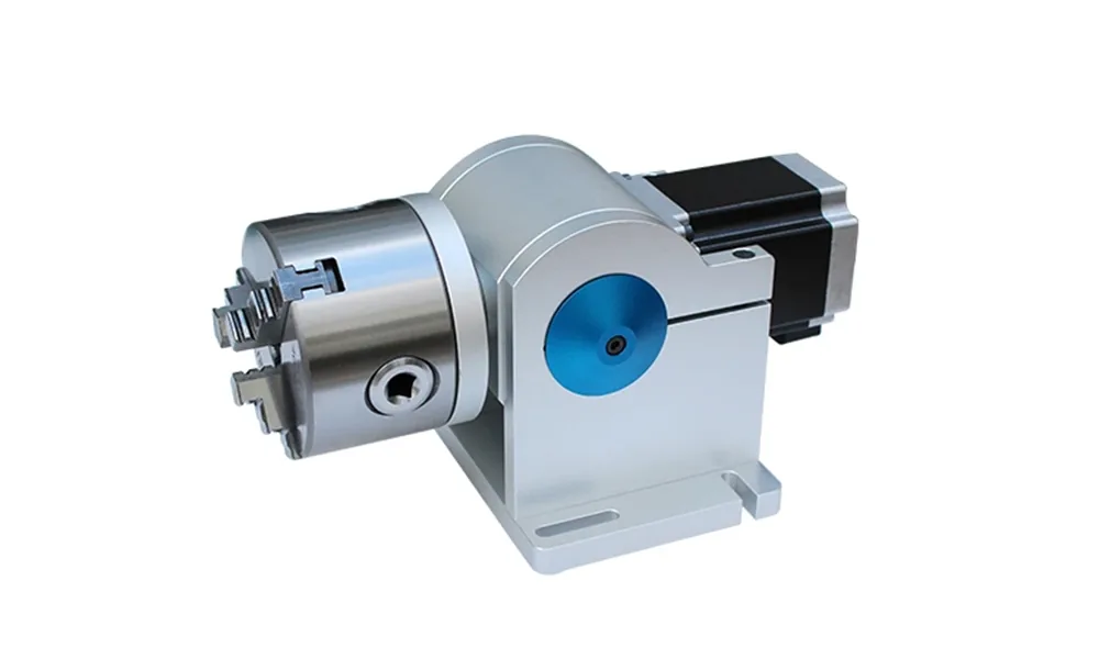
Cylindrical or annular geometry can require repeatable orientation, controlled clamping and a decision between a local stationary mark, rotary handling or 3D compensation.
- Serial and build identity
- Maintenance or overhaul reference
- Readable codes on limited zones
Combustor and Nozzle Components
High-temperature alloys, formed surfaces, protective coatings and thermally exposed conditions require the marking effect to be evaluated against the actual finished component.
- Part and batch identification
- Assembly orientation references
- Inspection record linkage
Cases, Housings and Supports
Larger components may provide more area but introduce cast or machined surface variation, recessed locations, mixed heights and fixture or access constraints.
- Part number and serial
- Data Matrix or QR data where permitted
- Service and repair traceability
Why Mark
Why Are Aerospace Engine Components Marked?
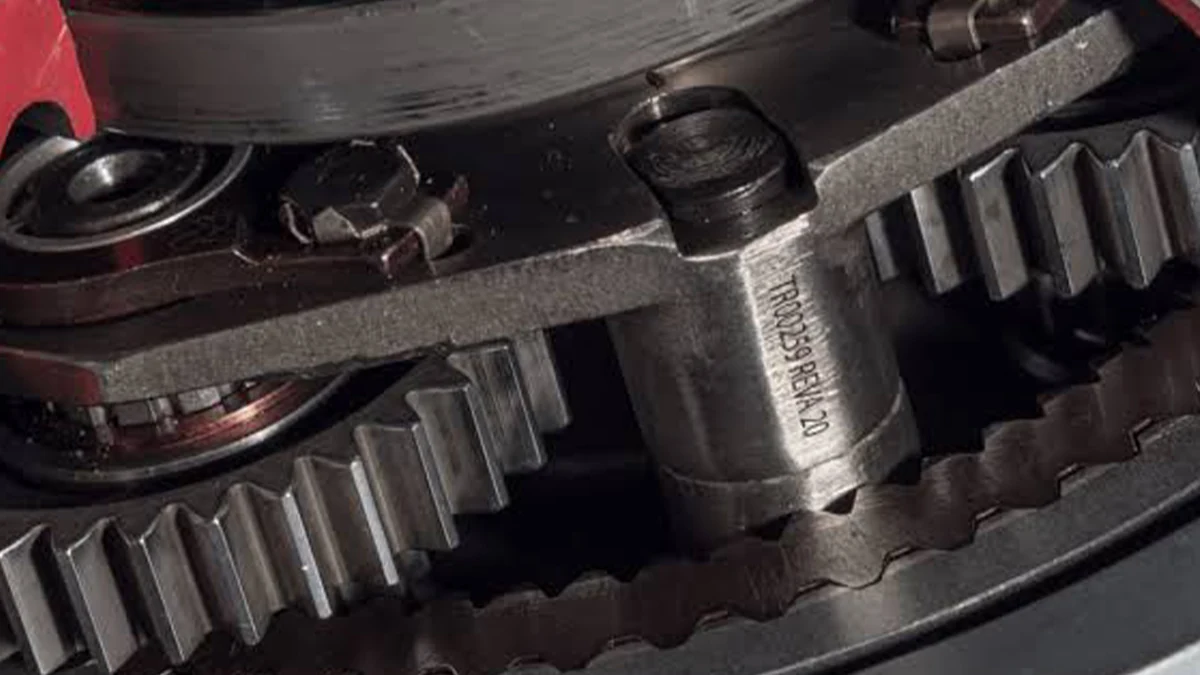
The mark is useful only when it supports a defined identification, traceability or lifecycle-control task. The drawing or quality system determines which identifiers are required and how they must be verified.
Part number and revision information help associate the physical component with the correct engineering configuration and approved record set.
A serial number can distinguish one component from another when manufacturing, inspection, service or lifecycle records must follow the individual part.
Lot, batch or heat references can connect the part to material or process records when those references are required by the controlling system.
Authorized identifiers can help connect a component to inspection, repair or overhaul records without relying only on loose documentation.
Where permitted, Data Matrix or other codes can support faster retrieval, verification and record association when the code size, reader and acceptance method are defined.
Clear, correctly placed identification helps reduce the risk of confusing visually similar parts, revisions or service states during controlled handling.
Identification Task
What Is Marked on Aerospace Engine Components?
Once the purpose is clear, freeze the exact content, location, data source and inspection method. A visually dark mark is not automatically the correct engineering result.
| Mark content | Inputs to freeze | Acceptance focus |
|---|---|---|
| Part number and revision | Approved characters, location, orientation and revision source | Correct content, placement and legibility |
| Serial number | Format, data source, duplicate-control rule and record association | Unique data and correct record linkage |
| Lot, batch or heat reference | Required format, retention needs and downstream database use | Accurate data capture and readable retrieval |
| Data Matrix or other machine-readable code | Code content, cell size, quiet zone, verifier, lighting and grade target where required | Defined verification result before and after required exposure tests |
| Inspection, overhaul or service reference | Permitted field, wording, revision and responsibility for updating | Readable, authorized and associated with the correct service record |

Result Variables
What Determines the Marking Result?
The alloy name is only one input. A useful sample plan combines the actual material and surface with the required mark effect, part geometry, positioning method, data task, verification method and production conditions.
| Variable | What must be defined | Why it changes the test |
|---|---|---|
| Material and condition | Alloy grade or family, heat treatment and relevant prior processing | Material condition can change the usable process window and the limits that must be respected on the finished part. |
| Surface state | Coating, oxide, machining or blasting history, roughness, contamination and cleanliness | The laser interacts with the actual surface presented to it, so nominally similar parts can produce different contrast or surface effects. |
| Required mark effect | Contrast, coating interaction, shallow material change, permitted depth and prohibited thermal or edge effects | The process should be selected against the required engineering outcome, not against darkness alone. |
| Geometry and section | Curvature, local height change, wall or edge condition, recessed access and available marking area | Geometry affects focus, optical access, distortion and whether a flat sample represents the production part. |
| Positioning and handling | Datum, fixture, orientation, clamp contact, part protection and repeatable loading | A stable laser process can still fail if the mark moves outside the permitted zone from part to part. |
| Mark content and size | Character height, line width, code cell size, orientation and variable-data structure | Fine codes and small characters demand a tighter combination of focus, spot behavior, motion and verification. |
| Verification method | Human readability, code reader, verifier, lighting, inspection timing and downstream reinspection | The test must produce evidence using the same type of acceptance method expected in production. |
| Production conditions | Volume, takt target, data changes, loading method, reject handling, extraction and operator interface | The final system must satisfy the complete production cycle, not only the optical marking time. |
Target Result
What Should an Acceptable Engine-Component Mark Achieve?
Acceptance should be defined before testing. There is no single universal visual target for every aerospace engine component; the relevant drawing, specification and quality plan determine which criteria apply and how they are measured.
Part, serial, lot, revision or service data must match the authorized source with no duplication or transcription error.
The mark must remain inside the permitted zone, with the required orientation and clearance from restricted features or surfaces.
Human-readable text must remain legible at the size and surface condition specified for the project.
Machine-readable codes should be checked with the defined reader, verifier, lighting and acceptance method where verification is required.
Contrast, depth, roughness change, raised material or thermal effect must stay within the limits allowed for the actual marking zone.
Where a coating is present, confirm whether the process is intended to modify the coating, remove it locally or preserve it, and inspect the underlying surface accordingly.
If cleaning, thermal exposure, corrosion, wear or other downstream tests are specified, the mark should be reinspected after those tests.
Representative parts should show stable mark quality and location across repeated loading rather than one isolated successful sample.
Geometry and Access
How Do Curved Surfaces and Part Handling Affect the Mark?
A flat sample can confirm a material direction, but it may not prove that the production mark remains focused, undistorted and correctly placed across a curved or height-varying engine component.
Working-Distance Variation
A curved blade, ring or housing can move parts of the marking area away from the nominal focal plane. The usable approach depends on curvature, mark size, required line or cell quality and available optical depth.
Fixture, Datum and Orientation
Repeatable datum location matters when the allowed zone is small or sits near an edge, feature, coating transition or critical surface. The fixture must hold orientation without damaging the part.
Code Geometry and Optical Access
Characters or Data Matrix cells can distort on a curve, while recessed zones can add optical access or collision constraints. Verification should be performed on the actual marked part under the intended reading conditions.
| Part geometry | Typical concern | What to evaluate |
|---|---|---|
| Small local curve with stable datum | Focus variation across a compact mark | Fixture stability and optical-depth review; evaluate 3D curved-surface marking when height variation exceeds the usable local focus range. |
| Cylindrical shaft or ring | Mark wraps around circumference or changes angle | Indexed positioning or rotary handling depending on required angular coverage and location repeatability. |
| Mixed part positions or variable features | Mark location changes by loading or part variant | Improve the datum and fixture first; evaluate vision-assisted positioning when location variation remains a real production variable. |
| Recessed or access-limited zone | Optical access, collision, shadowing or extraction | Confirm mechanical access, safe clearance and extraction layout before finalizing optics or motion. |
First-Test Laser Route
Which Laser Route Should Be Tested First?
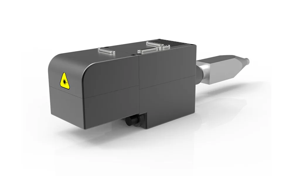
For metallic engine components, fiber-based marking is a practical first screening direction when the required effect and marking method are permitted. The purpose of the first test is to establish a workable process window on the real surface—not to lock the final machine configuration before evidence exists.
1. Confirm what the process is allowed to change
Start with the drawing or specification: define whether the target is surface contrast, coating interaction or shallow material change, and state any prohibited depth, heat, edge or critical-surface effects.
Review the requirement2. Screen a fiber-based metal-marking route
Use representative surface conditions to compare whether a fiber process can achieve the required contrast, edge quality and permitted surface effect without treating power alone as the selection criterion.
View fiber machine direction3. Expand pulse-control testing only when the result demands it
If the acceptable window is narrow, compare suitable pulse-control options within the fiber family, including MOPA-type sources where relevant, rather than assuming one pulse condition fits every alloy, coating or finish.
Discuss comparative sample testing4. Move from process screening to the finished geometry
After the surface effect is promising, repeat the test on the actual curved or height-varying part to validate focus, placement, code shape, fixture repeatability and complete cycle performance.
Review geometry and handling optionsFailure Diagnosis
Common Failure Modes and What They Usually Point To
A failed sample is useful when the visible symptom is connected to a testable cause. Check the easiest-to-separate mechanical, surface, optical and data variables before changing multiple laser parameters at once.
| Observed problem | Candidate causes to check | How to confirm |
|---|---|---|
| One side of a curved mark is sharp while the other side fades or broadens | Working-distance variation, local curvature, part height or insufficient focus tolerance | Map the surface height across the mark, repeat at controlled focus positions and compare with a smaller marking zone or suitable 3D compensation test. |
| Characters or Data Matrix cells distort toward the edge of the mark | Projection onto the curved surface, orientation error or optical/field geometry | Compare the same artwork at a flatter local zone, change orientation or evaluate rotary/3D handling while keeping mark content constant. |
| Mark position shifts between parts | Datum inconsistency, fixture clearance, loading variation or part-to-part geometry change | Measure the part location before marking, repeat controlled loading and separate fixture repeatability from laser-position accuracy. |
| Contrast varies across nominally similar parts | Surface finish, oxide, coating thickness, contamination or material-condition variation | Record actual surface condition, clean or group samples consistently and compare under the same optical settings before changing the process. |
| Contrast is acceptable but the surface effect is too aggressive | Energy density, pulse behavior, pass strategy or an incorrect target mechanism | Inspect depth or surface change using the project-required method and compare lower-effect process windows rather than judging darkness alone. |
| Coating is damaged outside the intended result | Coating variability, incorrect interaction target, focus/energy distribution or excessive overlap | Confirm coating condition and intended mark mechanism, then inspect the substrate and coating edge on representative finished parts. |
| A flat coupon works but the production component does not | Geometry, actual finish, restricted access, focus variation, fixture or different surface history | Repeat the same candidate route on the finished component and isolate geometry/handling changes before concluding the material route failed. |
| The mark passes initially but fails after a required downstream test | Insufficient durability, unsuitable surface effect or acceptance criteria that did not include the real exposure condition | Repeat the specified exposure and reinspection sequence, then compare pre- and post-test results using the same acceptance method. |
Production Workflow
What Must the Production Marking Workflow Include?
Production readiness is the complete controlled cycle around the mark. The laser scan time is only one part of the takt.
Protect the finished part and present it to the fixture in a repeatable state.
Seat the defined datum, confirm orientation and establish the marking zone.
Retrieve or enter the correct part, serial, lot, revision or code data and apply duplicate-control rules.
Run the approved recipe within the released process window for the actual part condition.
Check content, placement and code or visual quality using the specified inspection method.
Store the required production, verification or traceability record when the quality system calls for it.
Define how failed identification, failed verification or loading errors are contained and prevented from continuing as accepted production.
Remove the part without damaging the marked or critical surface and prepare the station for the next controlled cycle.
Sample Test and Acceptance
How Should Engine-Component Samples Be Tested and Accepted?
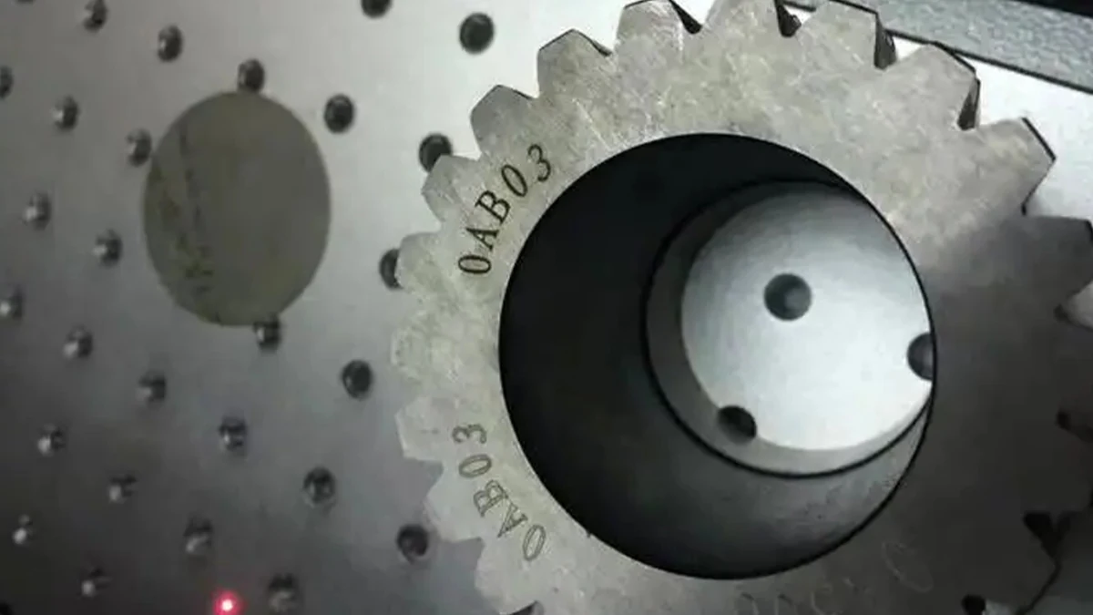
Use representative finished parts to prove both the mark result and the production method. Acceptance remains tied to the applicable drawing, specification and customer quality process.
Freeze the controlling inputs
Record the drawing or specification, mark restrictions, location, alloy, heat treatment, coating, surface finish, code requirements and critical-zone limits.
Use representative samples
Test the finished surface and geometry, including normal production variation rather than relying only on a polished flat coupon.
Compare candidate process windows
Change one meaningful process variable at a time where practical and record contrast, edge quality, surface effect, code result and location repeatability.
Run required downstream exposure
Apply the cleaning, thermal, corrosion, wear or other project-required tests, then reinspect the mark using the same defined acceptance method.
| Acceptance check | What should be recorded before release |
|---|---|
| Identity and data | Correct characters or code content, data source, duplicate-control result and record association where applicable. |
| Location and orientation | Measured or inspected placement against the permitted marking zone across repeated loading. |
| Visual or code quality | Legibility or verifier result using the defined lighting, reader and inspection method. |
| Surface effect | Project-required evidence for depth, roughness, coating condition, thermal effect or other restricted surface change where those criteria apply. |
| Post-exposure condition | Result after any required cleaning, thermal, corrosion, wear or other downstream test. |
| Repeatability | Results across representative parts and repeated fixture loading, not only one best sample. |
| Cycle feasibility | Complete process time including handling, data, verification, recording and reject logic against the production target. |
Final Machine Configuration
How Do Sample-Test Results Determine the Final Machine Configuration?
The final machine should be the result of the sample evidence. Each configuration choice answers a specific problem found during process, geometry, verification or cycle testing.
| What the sample or cycle test shows | Configuration direction to evaluate | Decision question |
|---|---|---|
| Process / Laser | ||
| The required metal mark is stable across the representative surface condition | Confirm the suitable fiber source class and power range without adding unnecessary complexity | Does the tested source provide enough process margin while staying inside the permitted surface-effect limits? |
| The result is sensitive to pulse condition or the acceptable window is narrow | Evaluate finer pulse-control capability within the fiber family, including MOPA-type options where relevant | Does additional pulse control improve repeatability or reduce unwanted surface effects on the actual part? |
| Small characters or codes require tighter optical detail | Review optics, spot behavior and working-field size together | What field size preserves the required detail while still covering the real marking zone? |
| Geometry / Positioning | ||
| Part location is repeatable but the allowed mark zone is small | Use a controlled fixture and datum strategy | Can fixture repeatability hold the mark inside the permitted zone without vision assistance? |
| The mark must extend around a shaft, ring or cylindrical surface | Evaluate indexed or continuous rotary handling as appropriate to the task | How much angular coverage is required, and what orientation accuracy must be maintained? |
| Height variation across the required mark exceeds the useful local focus range | Evaluate 3D focus compensation or revise the part/mark presentation | Can the required mark stay focused and geometrically correct across the full surface? |
| Loading variation changes the mark position or different variants present different features | Improve fixture control first, then evaluate vision-assisted positioning where it adds measurable value | Is the position error caused by loading, part variation or an unstable datum? |
| Verification / Data | ||
| Code verification is part of acceptance | Add the required reader/verifier, lighting and result handling | Must the system only read the code, verify against a defined criterion, or also save the verification result? |
| Serial or code content changes by part | Define the data interface, recipe/data association, duplicate prevention and record storage | Where does the production data originate, and how is the correct part-to-data relationship confirmed? |
| Production System | ||
| Manual handling cannot meet the complete production takt or consistency target | Evaluate assisted loading, motion or a more automated cell together with extraction and enclosure needs | Which part of the measured cycle—not just the laser scan—is limiting throughput or repeatability? |
| Process plume or residue affects the part, optics or working environment | Size extraction and enclosure around the actual process and part presentation | Where must fumes or particles be captured without interfering with access, marking or verification? |
Next Step
Build the Engine-Component Test Brief Before Selecting Equipment
Share the finished part, controlling requirements and production context so Zhuorui Laser can test the marking route, document the acceptance result and configure the source, optics, fixture, positioning, verification and machine format around the evidence.
Prepare: drawing/specification · alloy and heat treatment · coating/finish · marking zone · content/code size · target result and prohibited effects · part geometry · verification method · production volume and takt · data connection · representative samples.