
Online marking for moving products
Flying Laser Marking Machines
Mark dates, batch codes, serial numbers, logos and traceability information while products move through a production line. Compare Fiber, UV and CO2 flying routes, then match the controller, trigger, encoder, marking field and mounting arrangement to your actual line.
- Fiber, UV and CO2 flying routes
- Sensor, trigger and encoder matching
- Inline mounting and working-distance review
- Sample and line-condition validation
How flying marking works
What Is a Flying Laser Marking Machine?
A flying laser marking machine is configured to create the mark while the product continues moving. The controller uses a product trigger and, where required, a speed reference such as an encoder so the scan can be synchronized with product motion.
This is different from a standard static marking station, where the part is held still during the laser scan. It is also useful to separate flying from the broader terms online or inline: an inline station can be installed on a production line but may still stop or index the part before marking. Flying marking specifically refers to marking during motion.
Benefits and trade-offs
Why Choose a Flying Laser Marking Machine?
The main advantage is not simply “higher speed.” Flying marking changes how the marking process fits into production: the product can continue moving while the laser completes the required code or graphic.
Key Benefits
Keep Product Flow Moving
For suitable lines, the mark can be applied without creating a separate stop for every part. This can simplify high-throughput coding and traceability tasks.
Handle Variable Production Data
Dates, batch numbers, serial numbers and other changing content can be updated through the marking software or the agreed data interface.
Integrate Above Existing Conveyors
The marking head, controller and sensor package can be mounted around an existing conveyor when space, working distance and guarding are suitable.
Reduce Extra Part Handling
Products that are already oriented on a line may not need to be removed, manually placed and returned solely for marking.
Main Limitations
Trade-off: Synchronization
The mark can distort if product speed, trigger timing or encoder scaling does not match the controller configuration.
Trade-off: Stable Product Position
Large variation in height, lateral position or product orientation can require extra guidance, vision or a different process layout.
Trade-off: Limited Marking Window
Line speed, product spacing and code complexity determine how much time is available for each mark. Rated galvo scan speed alone does not define the production result.
Trade-off: Safety and Fumes
Open conveyor installations need an installation-specific review of beam access, guarding, interlocks and fume extraction for the actual material.
Flying machine types
Flying Laser Source Options: Fiber, UV and CO2
Flying machines can be configured around different laser wavelengths. Fiber, UV and CO2 share the same online-marking purpose, but they interact with materials differently. Start with the real material and required mark before confirming optics, controls and installation.
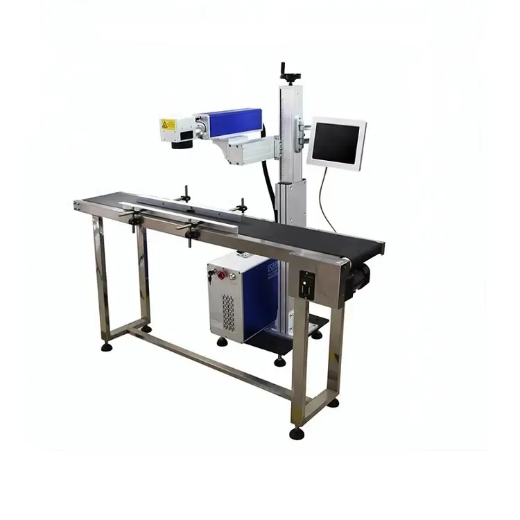
Fiber flying route
Flying Fiber Laser Marking Machine
A common starting route for metals, coated metals and selected plastics where a fiber source produces the required contrast or surface effect.
Explore Fiber Laser Marking Machines →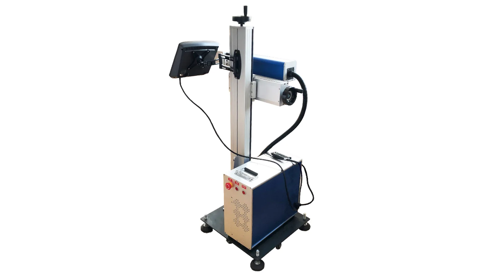
UV flying route
Flying UV Laser Marking Machine
Consider UV when the application needs a different wavelength response or lower heat input on compatible plastics, films, electronics and other sensitive surfaces.
Explore UV Laser Marking Machines →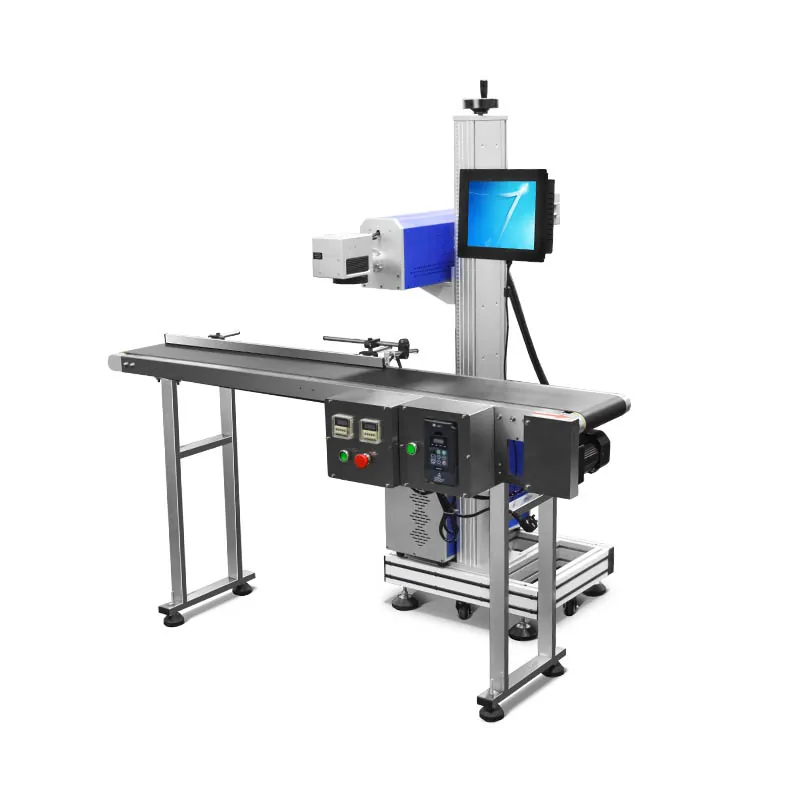
CO2 flying route
Flying CO2 Laser Marking Machine
A common route for suitable paper, cardboard, coated packaging, films and organic materials where CO2 absorption creates the required code or surface change.
Explore CO2 Laser Marking Machines →Size and installation confirmation
How to Confirm Product, Marking and Installation Dimensions
For a flying machine, “size” is not only the machine footprint. Product dimensions, mark size, optical field, working distance and conveyor clearance all affect whether the head can be mounted and whether the mark can remain inside a stable working window.
| Dimension group | What to provide | Why it matters |
|---|---|---|
| Product envelope | Product length, width, height, surface to be marked and expected height variation. | Confirms whether the product can pass through the marking zone with a repeatable surface position. |
| Required mark size | Actual width and height of text, logo, barcode, Data Matrix, date, batch or serial content. | The real mark size is the starting point for field and lens selection; conveyor width alone does not define the optical field. |
| Marking field | Required usable field plus the smallest feature or code element that must remain readable. | A larger field is not automatically better. Field size changes focal distance and can affect spot size and small-feature performance. |
| Working height | Conveyor surface height, product top-surface height, lens-to-marking-surface distance and any height adjustment required. | The marking head must keep the actual surface within the usable focus range throughout production. |
| Installation envelope | Conveyor width, available space above and beside the line, bracket area, controller location, service clearance and guarding space. | Determines whether the machine can be mounted rigidly without interfering with product flow, operators or maintenance access. |
Laser source comparison
Fiber vs UV vs CO2 for Flying Laser Marking
Do not choose the source from line speed or wattage alone. The correct route starts with how the actual production surface responds and what mark must be accepted.
| Laser route | Common starting materials | Why it may fit | What must be tested |
|---|---|---|---|
| Fiber | Metals, coated metals and selected engineering plastics | Strong fit for many permanent metal codes and traceability marks. | Surface finish, contrast, depth or colour requirement, smallest feature, line speed and focus stability. |
| UV | Selected plastics, films, electronics materials and other heat-sensitive surfaces | Useful when wavelength response and reduced thermal input are more important than simply increasing power. | Exact formulation, colour, thermal response, haze or residue, required code quality, cooling and available marking time. |
| CO2 | Paper, cardboard, coated packaging, selected films, wood and other compatible organic materials | Longer-wavelength absorption can create coding or surface-change effects on many non-metal production materials. | Layer construction, coating, burn-through risk, plume, extraction, contrast and line-speed compatibility. |
Machine structure comparison
Flying vs Other Laser Marking Machine Structures
Flying marking is a production-line structure, not a universal upgrade over every other machine format. Compare how the workpiece is presented, whether it moves during marking and how much positioning control the process needs.
| Machine structure | Part condition during marking | Best starting point | Main trade-off / confirmation |
|---|---|---|---|
| Flying / online | Product continues moving through the marking zone. | Continuous conveyors, extrusion lines, packaging lines and other processes where stopping every product is undesirable. | Needs stable product presentation, reliable trigger/speed information and enough marking time inside the available window. |
| Desktop / split workstation | Part is stationary during marking. | Operator-loaded parts, small batches, fixtures and flexible workstations. | Requires loading and positioning time, but gives a simpler stationary marking condition. |
| Enclosed workstation | Part is stationary inside a defined work area. | Dedicated operator stations where guarding, access control and extraction need to be organized around the marking area. | Loading opening, part clearance, interlocks and the complete safety configuration must match the actual process. |
| Portable machine | Machine can be relocated; the part is normally stationary while marking. | Changing work areas, service tasks or workpieces that are inconvenient to bring to a fixed workstation. | Repeatable positioning, focus control, cable management and site safety become more dependent on setup. |
| Handheld marking | Operator moves the marking head to a large or fixed workpiece. | Large structures or parts that cannot be loaded onto a conventional table. | Operator positioning, focal distance, repeatability and guarding are harder to standardize than with a fixed marking head. |
Vision, rotary and 3D are different decision axes
CCD vision, rotary fixtures and 3D dynamic-focus functions can be combined with different machine structures. They should not be treated as direct structural substitutes for flying equipment.
Marking performance
What Determines Marking Quality on a Moving Line?
A successful flying setup depends on the complete time-and-position window. The same laser and artwork can behave differently when the material, product motion or installation geometry changes.
Material & Surface
Grade, formulation, colour, coating and surface condition determine how the laser energy produces contrast, ablation or another visible effect.
Code Size & Complexity
Large graphics, dense 2D codes and small features can require more scan time or tighter process control than short text or simple dates.
Line Speed
Higher product speed shortens the available marking window. The correct limit must be evaluated with the actual code, field and material response.
Product Spacing
Spacing determines how much time exists between one product event and the next and whether the controller can complete and reset the sequence reliably.
Focus & Height Stability
Variation in product height changes the spot at the surface. Excessive height variation can reduce edge definition, contrast or code readability.
Trigger & Motion Accuracy
Incorrect trigger position, unstable speed information or poor encoder scaling can shift or stretch the mark even if the laser parameters themselves are unchanged.
Selection boundary
When Flying Marking Is Not the Best Choice
A simpler workstation or a different integration route can be better when the production line cannot provide the stability that flying marking needs.
Low-Volume Manual Production
If operators already load parts individually and line throughput is not the constraint, a static desktop or enclosed workstation may be simpler.
Large Position or Height Variation
Random part orientation, large lateral movement or large height differences can exceed what a basic flying setup can correct.
Long Marking Time per Part
Large filled graphics, deep engraving or other long processes may not fit the available time between products at the required line speed.
Unresolved Safety or Fume Control
If the site cannot establish suitable guarding, access control or extraction for the actual process, the installation should not be treated as ready for production.
Unstable Conveyor Speed or Product Presentation
If products arrive with unpredictable spacing, orientation or height, or the line cannot provide a reliable trigger or speed reference, a basic flying setup may not maintain mark position consistently.
Typical supply scope
What Is Included with a Flying Laser Marking Machine?
The exact package depends on the selected laser source and the production line. The quotation or configuration sheet should define the final scope; the groups below show what normally needs to be confirmed before the machine is released.
Core Marking Package
Laser source, galvo scanning head, F-theta lens, controller, electrical components and the machine structure required for the selected route.
Flying Control Package
Product-trigger input, sensor provisions, encoder or speed-reference capability where required, production-data interface and defined I/O functions.
Mounting & Utilities
Marking-head support or bracket, height adjustment, required cables, cooling arrangement and extraction interface according to the final installation.
Setup & Documentation
Basic software setup, operating documentation, configuration confirmation and pre-shipment functional checking for the agreed machine package.
Confirm optional items on the quotation
Sensors, encoders, special brackets, conveyor modifications, vision, inspection, reject handling, extraction equipment, guarding and PLC/MES integration should be listed separately when they are required. They are not assumed to be included in every standard flying machine.
Typical applications
Where Flying Laser Marking Is Commonly Used
The equipment route should follow the product, material and required code rather than the industry name alone.
Packaging & Coding
Date codes, batch information, lot numbers, serial data and graphics on suitable cartons, labels, films, bottles, caps and other packaging surfaces.
View Packaging & Coding Applications →Wire, Cable & Tubing
Continuous identification and production codes on compatible cable jackets, wire insulation, heat-shrink and tubing materials.
View Wire, Cable & Tubing Applications →Electronics & Electrical Parts
Traceability marks on suitable housings, connectors, components and production parts where product guidance and focus can be controlled.
View Electronics & Electrical Applications →Metal Components
Serial numbers, lot codes and identification marks on suitable moving metal parts when the line can present the marking surface consistently.
FAQ
Flying Laser Marking Machine FAQ
What is the difference between flying and online laser marking?
Online or inline means the marking equipment is installed as part of a production line. Flying marking is more specific: the mark is created while the product continues moving. An inline station that stops or indexes the part before marking is online, but it is not necessarily flying.
Do I always need an encoder for flying laser marking?
Not always. A fixed-speed process may use a validated fixed-speed setup in some configurations, while variable-speed lines commonly need a reliable speed reference such as an encoder. The correct method depends on the controller and how the production line behaves.
Can a flying laser marking machine be installed on an existing conveyor?
Often it can be evaluated as a retrofit, but the available mounting space, working distance, product guidance, sensor position, encoder or speed signal, PLC interface, guarding and extraction all need to be checked first.
How do I choose between Fiber, UV and CO2?
Start with the exact material, surface construction and required mark. Fiber is commonly used for metals and selected plastics, UV for selected heat-sensitive plastics, films and electronics materials, and CO2 for many packaging and organic materials. Test the real production surface before confirming the source.
Does a faster galvo mean the production line can run faster?
No. Galvo scan speed is only one variable. Code size, fill density, material response, line speed, product spacing, trigger timing, focus stability and controller synchronization all affect the available production window.
Can one flying machine mark every material?
No. Different wavelengths interact differently with metals, polymers, coatings, films and organic materials. The machine should be selected around the actual material and required result rather than assuming one source is universal.
What information should I provide for a quotation?
Send the material and product, mark content and size, line speed, product spacing, mark position, conveyor dimensions, available mounting space, product sensor, encoder or PLC information, power supply and any extraction or guarding requirements.
RFQ
Request a Flying Laser Marking Machine Quote
Send the real product and line conditions so the machine can be matched around the material, mark size, available marking time and installation space instead of being selected by wattage alone.
- Product and material: product photos, material, surface or coating, and representative samples where available.
- Product dimensions: length, width, height, marked surface and expected height variation.
- Required mark: text, logo, barcode, Data Matrix, QR code, date, batch or serial content, including the actual mark size.
- Production conditions: normal and maximum line speed, product spacing and whether speed is fixed or variable.
- Mark position: where the mark must land, available marking area and product orientation through the marking zone.
- Installation dimensions: conveyor width, working height, available head/bracket space, controller location and service clearance.
- Controls: available sensor, encoder or speed reference, PLC I/O and variable-data connection requirements.
- Site conditions: power supply, cooling, extraction, guarding space and operator access.