
Camera-guided laser marking
Vision CCD Laser Marking Machines
Use camera-guided positioning when parts can shift or rotate inside the marking area and the laser mark must follow a visible feature, contour or datum. Zhuorui configures Vision CCD laser marking machines around the workpiece, field of view, lighting, laser source, fixture and required positioning method.
- Camera, lens and lighting matched to the part
- Fiber, UV, CO2 and custom vision routes
- X/Y position and rotation compensation
- Sample-based recognition and marking validation
Vision marking overview
What Is a Vision CCD Laser Marking Machine?
A Vision CCD laser marking machine adds a camera-based positioning layer to a conventional galvo laser marking system. The camera locates a feature on the workpiece, software calculates the required offset or rotation, and the marking controller applies that correction before the laser marks the part.
The key benefit is not simply “having a camera.” It is reducing dependence on exact manual placement when the part can move within a controlled viewing area. This is useful for small parts, mixed orientations, nests and other jobs where the mark must stay registered to a visible feature.
Vision positioning mainly solves X/Y location and rotational alignment. Height variation, curved surfaces and changing focal planes are separate problems and may require autofocus, Z-axis compensation, 3D optics or a different fixture strategy.
Selection decision
Why Choose Vision — and When a Fixture Is Better
Vision is valuable when the datum moves. If the part is already repeatably located by a simple fixture, adding a camera can increase cost and complexity without improving the result.
Choose Vision CCD When
- Parts can shift in X/Y inside a known loading area.
- Part rotation changes between cycles.
- Several parts share one image or nest.
- The mark must follow a hole, edge, contour or printed feature.
- Part identity may select different marking content.
- A wrong or uncertain recognition result must stop the marking cycle.
Consider Another Route When
- Stable fixture: every part arrives on the same repeatable datum.
- Height changes: the main issue is focal distance rather than X/Y position.
- Curved surfaces: the mark must follow significant 3D geometry.
- Continuous motion: products move through the marking point at production speed.
- Poor visual feature: glare, transparency or weak contrast prevents reliable recognition.
For production-line synchronization, review the vision positioning solution together with the required line control and reject logic.
System components
What Makes Up a Vision CCD Laser Marking System?
Recognition quality is created by the complete imaging and marking chain. Camera resolution alone does not determine positioning performance.
Camera
The camera captures the work area and the reference feature used for positioning. Resolution matters, but usable recognition also depends on the lens, field of view, working distance and feature size.
Lens & Field of View
The lens determines how much area the camera can see and how large the reference feature appears in the image. A wider field covers more area but generally gives fewer pixels to the same small feature, so FOV and feature size must be selected together.
Lighting
Lighting makes edges, contours, holes or printed features stable enough for recognition. Reflective metals, dark plastics and transparent surfaces may require different illumination geometry and glare control.
Calibration
Calibration maps camera coordinates to the galvo marking field. Lens distortion, working height and mechanical stability all affect whether the calculated correction reaches the intended marking position.
Vision Software & Recognition
The software detects the approved datum, contour, pattern or code, applies recognition thresholds and calculates position or rotation correction. No-match and low-confidence states should be handled explicitly.
Laser Source & Marking Optics
The laser source, galvo, field lens and focus create the mark after positioning is resolved. Vision controls where the mark is placed; it does not replace material and laser-process selection.
Camera, lens and lighting
Define FOV, Feature Size, Lighting and Calibration Together
The correct imaging setup starts from the real loading range and the feature the camera must recognize. A larger field of view is not automatically better if the smallest usable feature becomes difficult to resolve.
| Variable | What to define | Why it matters | Practical check |
|---|---|---|---|
| Allowed placement range | Maximum X/Y shift and rotation expected during loading. | This determines how much of the work area the camera must see. | Place representative parts at the center, edges and corners of the expected loading area. |
| Camera field of view | The visible area required to contain every allowed part position. | A wider FOV covers more area but reduces image detail per unit area for the same sensor. | Confirm that the smallest recognition feature remains clear across the usable field. |
| Recognition feature | Hole, contour, corner, fiducial, printed mark, pattern or code. | The feature must be visually stable enough to provide a repeatable datum. | Test clean parts plus normal surface variation, orientation and background conditions. |
| Lighting | Direction, intensity and geometry of the illumination. | Glare and low contrast can move or hide the apparent edge seen by the camera. | Compare images under the proposed lighting with the actual surface finish. |
| Working height | Camera distance, laser focus plane and expected height variation. | Changing height can alter image scale, focus and laser marking focus. | Define the allowed Z range separately from X/Y positioning. |
| Calibration | Mapping between camera coordinates and the galvo marking field. | Good recognition does not guarantee a correct laser position if the coordinate mapping is wrong. | Validate multiple points across the real marking area, not only the center. |
Vision CCD machine categories
Choose from Fiber, UV, CO2, or Custom Vision CCD Machines
Vision handles part recognition and position correction, while the laser source determines how the material is marked. The main equipment routes are Fiber, UV and CO2. Custom Vision CCD machines are used when the project also needs non-standard optics, focus control, fixtures, motion, guarding or integration.
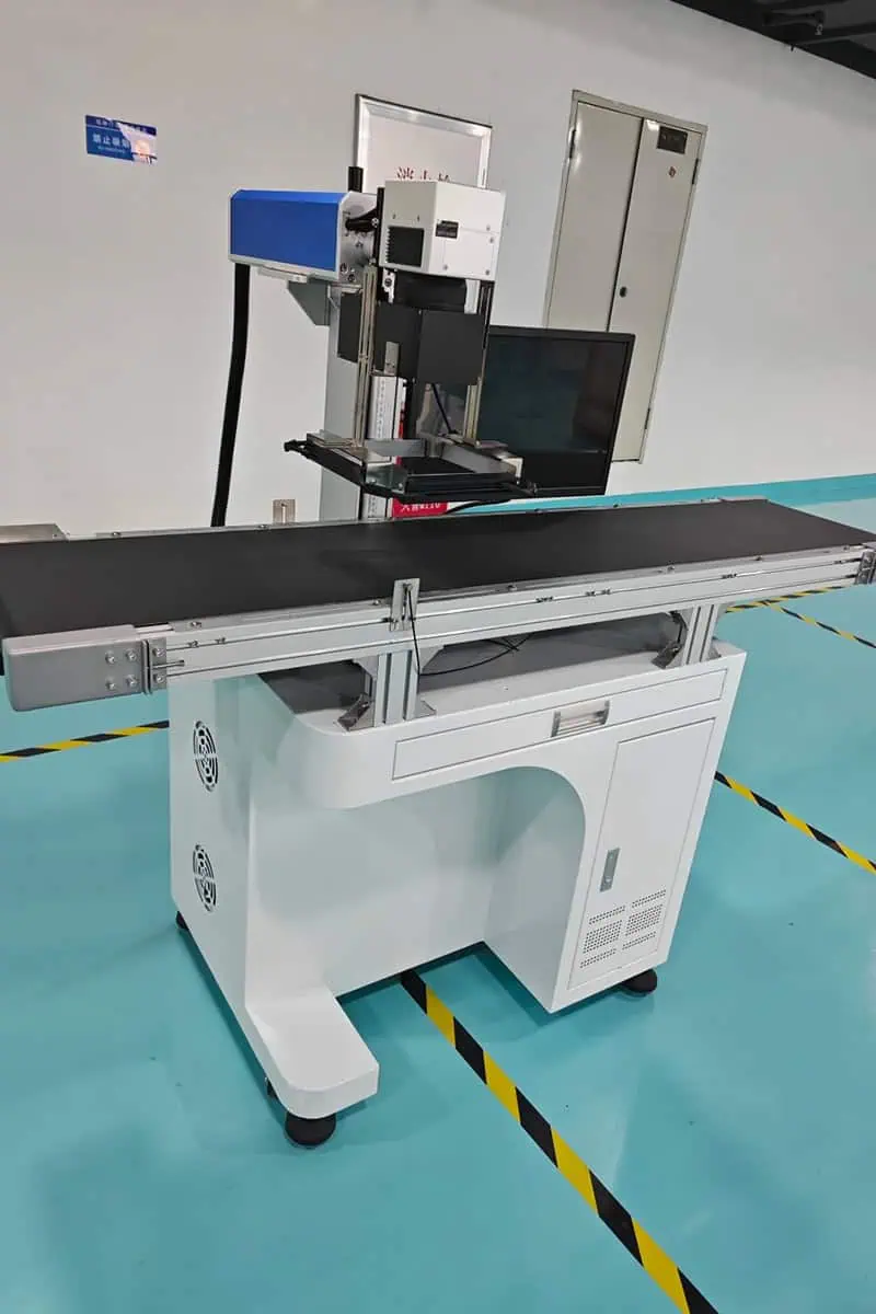
Fiber + CCD vision
Vision CCD Fiber Laser Marking Machine
For suitable metals, coated metals and selected engineering plastics where fiber laser processing gives the required contrast, depth or surface effect. The vision system corrects part position and rotation before the fiber laser marks.
Review Fiber Laser Marking Machines →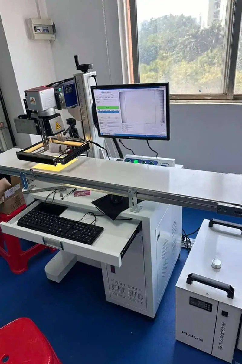
UV + CCD vision
Vision CCD UV Laser Marking Machine
For suitable plastics, electronics, glass and other applications where a UV process is selected for fine features or lower heat input. Camera, lens and lighting still need to be matched to the actual recognition feature and surface.
Review UV Laser Marking Machines →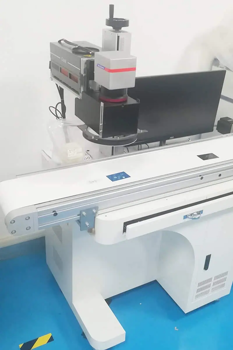
CO2 + CCD vision
Vision CCD CO2 Laser Marking Machine
For paper, wood, leather, packaging materials and other CO2-responsive non-metal applications when parts or printed features arrive with variable position or orientation. The vision task and CO2 marking process should be validated separately and then combined.
Review CO2 Laser Marking Machines →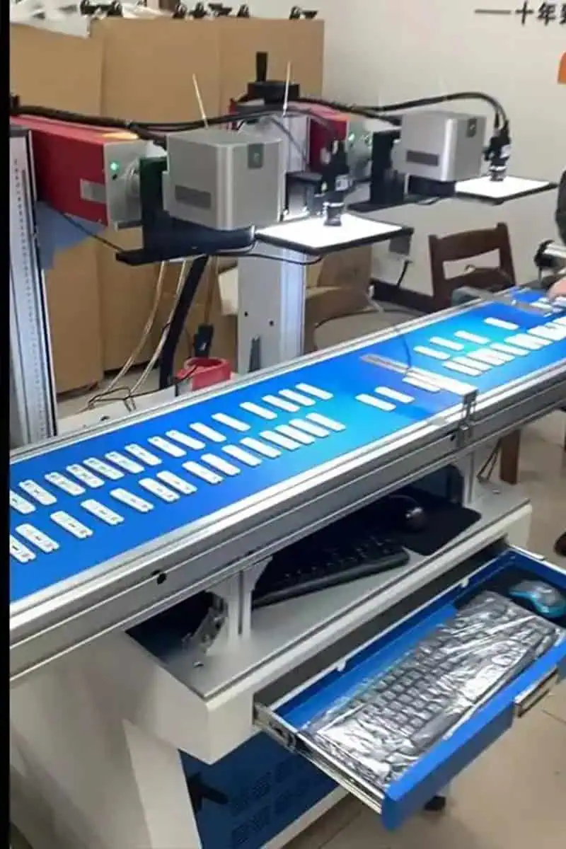
Custom Vision CCD
Custom Vision CCD Laser Marking Machine
For projects that need more than a standard camera-positioning station, such as special lighting, larger or unusual fields of view, autofocus or Z compensation, custom fixtures, rotary handling, special workstation structures, multi-part nests, conveyor interfaces or project-based automation.
Configuration note: “Custom” describes the project scope, not a fourth laser wavelength. The final machine may use Fiber, UV or CO2 according to the marking process.
Discuss a Custom Vision CCD Project →How vision marking works
From Camera Image to Laser Mark
For a standard vision workstation, keep the equipment workflow simple: acquire the image, locate the approved feature, convert that result into the laser coordinate system, mark, then perform any optional inspection required by the job.
Acquire the image
The camera captures the defined field under controlled lighting.
Find the datum
Software identifies the approved feature, contour or part orientation.
Calculate correction
The system converts the detected position and angle into marking coordinates.
Apply the laser mark
The galvo marks the approved content using the selected laser process.
Inspect or read
If required, a separate read or verification step checks the mark or production record.
Complex PLC/MES handoff, line synchronization, reject routing and multi-station automation belong to the project-level vision positioning solution review rather than the standard product-selection page.
Positioning validation
How to Validate Vision Positioning Before Purchase
Do not accept a camera-resolution number as a positioning-accuracy guarantee. Validate the complete camera, lens, lighting, calibration, mechanics and software setup on the real part and the real usable field.
Define the datum
Choose the feature the mark must follow and define the allowable positional error relative to that feature.
Test the whole field
Place the part at the center, edges and corners of the allowed loading area and include representative rotations.
Repeat recognition and marking
Run repeated cycles under the intended lighting and normal surface variation rather than one ideal image.
Measure the result
Measure the mark relative to the defined datum and record the actual configuration, test method and acceptance decision.
Evidence rule for measured accuracy: any published positioning value should be tied to the actual camera, lens, field of view, working height, calibration method, part feature and measurement method that produced it.
Typical use cases
Where Vision-Guided Laser Marking Adds Value
The best use cases have a visible, repeatable feature that the camera can locate and a marking requirement that would otherwise depend on tighter manual placement or more complex fixturing.
Loose Metal Parts in Trays
When small metal parts can shift or rotate inside a tray or loading area, the camera can locate a hole, edge, contour or machined feature and correct X/Y position and rotation before marking.
Electronic Components & Connectors
Use connector holes, housing edges, PCB reference points or other stable features to keep identifiers, logos or small text registered to the correct local position.
Labels, Packaging & Printed Features
When laser content must follow an existing print, label edge, cut line or packaging feature, vision can locate that visible reference and place the mark relative to it.
Multi-Part Nests
When several parts share one camera field, the system can locate each approved part, calculate a separate coordinate correction and then mark each position in sequence.
Configuration checklist
What to Confirm for a Vision CCD Laser Marking Machine
A useful quotation should connect the vision task to the laser process, mechanics, data flow and safety scope instead of specifying “CCD” as a single accessory.
| Area | Information to provide | Configuration to confirm |
|---|---|---|
| Workpiece | Material, surface finish, dimensions, photos/drawings, normal variation and loading method. | Fixture support, usable working height and camera visibility. |
| Recognition task | Feature to locate, allowed X/Y movement, rotation range, number of parts in one field and no-match behavior. | Camera, lens, FOV, lighting and recognition method. |
| Laser mark | Text, logo, serial number or code; mark size; smallest feature; required appearance or durability. | Fiber, UV or CO2 route; source subtype; field lens; and process testing. Use a custom machine scope when the optics, mechanics or handling are non-standard. |
| Height / geometry | Nominal marking height, allowed Z variation, stepped or curved surfaces. | Manual focus, Z-axis, autofocus, focus compensation or 3D route as required. |
| Data | Static artwork, serial data, barcode input, OCR requirement, external database or production record. | Software capability, controller, scanner/reader and I/O scope. |
| Production | Required cycle target, loading/unloading time, batch size and operator sequence. | Workstation layout, nests, triggering and whether project-level integration is needed. |
| Safety & destination | Destination voltage, required machine guarding, extraction, installation environment and local safety requirements. | Complete machine safety configuration, interfaces and included accessories. |
Do not confuse three functions
Positioning Camera, Code Reading and Code Verification Are Different
A CCD camera used for part positioning does not automatically provide barcode grading, OCR validation or traceability verification. Define the inspection task separately from the positioning task.
Vision Positioning Camera
Main job: locate a feature, contour, part or orientation and calculate marking coordinates.
Does not automatically prove: barcode grade, OCR accuracy or long-term mark readability.
Code Reading / OCR
Main job: read content such as characters, barcodes or Data Matrix when the imaging and software configuration supports it.
Still requires: defined contrast, focus, code size and pass/fail behavior.
Code Verification / Grading
Main job: evaluate a code against a defined verification method or quality requirement.
May require: a dedicated verifier, controlled illumination and an agreed standard or acceptance procedure.
Common buying questions
Vision CCD Laser Marking Machine FAQ
What does CCD vision add to a laser marking machine?
It adds a camera-based positioning layer. The system can locate an approved feature or part orientation, convert that result into laser coordinates and correct the mark position before marking.
Can a Vision CCD machine eliminate fixtures completely?
Not always. A light locating nest or support can still improve presentation, focus stability and cycle consistency. Vision is most useful when precise mechanical positioning is difficult or unnecessary, not when every mechanical reference should be removed.
Does a higher-resolution camera guarantee higher marking accuracy?
No. The result also depends on lens selection, FOV, lighting, feature contrast, calibration, working height, mechanics and the method used to measure the final mark position.
Can vision compensate for part height changes?
Standard 2D vision mainly corrects X/Y position and rotation. Height variation affects focus and may require Z-axis adjustment, autofocus, focus compensation or a 3D marking route.
Should I choose Fiber, UV, CO2 or a custom Vision CCD machine?
Choose Fiber, UV or CO2 from the workpiece material, surface condition and required marking result. Choose a custom machine scope when the project also needs non-standard optics, focus control, fixtures, motion, guarding or integration. The vision camera does not change the material response to the laser.
Can the same camera verify Data Matrix or barcode quality after marking?
Only when the imaging system, software and acceptance method are designed for that task. Positioning, code reading and formal code verification are different functions and should be specified separately.
What should I send for a Vision CCD quotation?
Send part photos or drawings, material and finish, the feature the camera should locate, allowed placement and rotation range, marking artwork, required field size, target cycle, height variation, data requirements and representative samples where possible.
Request a configuration review
Send the Part, Datum and Placement Range Before Choosing the Camera
Share the workpiece, surface, mark content, recognition feature, allowed X/Y movement and rotation, target cycle, height variation and destination requirements. Zhuorui can then review the camera, lens, lighting, laser source, marking field, fixture and workstation configuration around the actual task.