
Copper & Brass Laser Marking
Copper laser marking requires particular attention to high reflectivity, fast heat conduction, surface condition and any electrically functional areas on the part. Brass is included here as an important copper-zinc alloy family: it shares some reflective-metal challenges but adds further variation from alloy composition, polishing, plating, lacquer, patina and oxidation. For either material, the practical starting point is the exact grade or alloy, final surface and required mark result.
Start with the actual alloy, surface and acceptance target
The useful question is not simply “can a laser mark copper or brass?” It is whether the final part can produce the required contrast, depth, code readability or cosmetic finish without creating unacceptable heat, surface damage or functional change.
For copper, grade, thickness, oxide condition, coatings and conductivity-sensitive areas matter because the mark may sit on a busbar, terminal, connector, plate, foil or other functional component. For brass, alloy family, polish, plating, lacquer, patina and decorative finish can shift the process window. A setup that works on one surface should not be treated as a universal recipe for another.
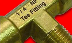
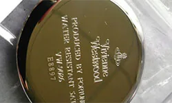
Copper and brass need separate process qualification
Brass contains copper, but it is not simply “copper with the same settings.” The zinc content, surface finish and coatings can change absorption, heat behavior, appearance and fume conditions. The comparison below keeps the two materials together without pretending they behave identically.
| Decision factor | Copper | Brass |
|---|---|---|
| Material identity | Pure copper, oxygen-free copper, busbar stock, foil or other copper grades/alloys should be identified when known. | Brass is a copper-zinc alloy family. Alloy composition can change the marking response, so the real production grade is preferred for testing. |
| Main process challenge | High reflectivity and fast heat conduction can make energy coupling and contrast more sensitive than on many steels. | Reflective copper-rich behavior remains relevant, while zinc content, polish, oxide, plating and lacquer can shift the usable process window. |
| Common surfaces | Bare, polished, brushed, oxidized, plated, lacquered, enamel-insulated, oiled or cleaned surfaces. | Machined, polished, brushed, plated, lacquered, aged, patinated or coated surfaces. |
| Typical parts | Busbars, terminals, connectors, battery-related conductive parts, foils, tags and electrical components. | Valves, fittings, locks, keys, nameplates, instrument parts, terminals, decorative hardware and small industrial parts. |
| Functional risk | Mark position, heat input, coating removal and contact areas may matter where electrical performance is part of acceptance. | Surface appearance, plating/lacquer integrity, corrosion exposure and decorative consistency may matter as much as mark visibility. |
| Validation focus | Contrast or depth, heat effect, warping on thin stock, scanner performance and any required electrical/functional checks. | Contrast, finish consistency, code readability, scratch/cleaning durability and the effect of polishing, plating or lacquer. |
Bare or polished copper
Polished copper can be difficult to couple into consistently. Test contrast, heat tint, edge definition and repeatability on the real finish.
Oxidized, plated or coated copper
The laser may interact with an oxide, plating, lacquer, paint or insulation layer before it reaches the copper. Layer chemistry and thickness can dominate the result.
Bare or polished brass
Polish level, alloy composition and existing oxide can change contrast and heat appearance. Decorative parts should be approved from the actual production finish.
Plated, lacquered or aged brass
On plated or lacquered brass, the surface layer may be the real processing target. Verify whether the goal is contrast, layer removal, shallow engraving or preservation of the finish around the mark.
Thin conductive parts and contact areas
Thin copper, foils, terminals and connector areas need careful heat and fixture control. Mark location should avoid functional contact zones unless the customer has approved the effect.
Oils, residues and unknown coatings
Residue can make a good parameter set look inconsistent and can change the fume profile. Record cleaning condition and obtain material or coating information when available.
Define the required mark before choosing the laser route
A visible logo, shallow engraving, decorative finish and machine-readable Data Matrix code are different engineering targets. The acceptance method should be defined before the machine configuration is finalized.
| Target result | Copper considerations | Brass considerations | Validation needed |
|---|---|---|---|
| Dark or high-contrast surface mark | Polish, oxide state, pulse behavior, cleaning and heat movement can change tone and uniformity. | Alloy, polish, patina, plating and lacquer can change both contrast and cosmetic appearance. | Approve appearance on the final surface; include cleaning or durability checks when relevant. |
| Shallow engraving | Depth target, thickness, heat input and number of passes affect edge quality, warping and cycle time. | Depth, burr, finish damage and color change around the engraving should be checked on the real alloy. | Measure depth if specified and inspect burr, heat-affected appearance and cycle time. |
| Coating, lacquer or plating removal | Layer chemistry, thickness and the exposed copper surface determine the final appearance and residue. | Useful on lacquered, painted or plated brass when controlled layer removal is the actual goal. | Check clean edge, residue, exposed substrate, extraction and downstream durability. |
| Serial number, QR code or Data Matrix | Glare, roughness, small cell size, focus and fixture repeatability can affect reading. | Curved fittings, polished hardware and coated surfaces can make contrast and code geometry more sensitive. | Test the real scanner, code size, reading distance and verification requirement when applicable. |
| Decorative or cosmetic mark | Viewing angle, oxidation and cleaning can change perceived tone. | Finish consistency is often critical on polished or plated decorative parts. | Approve a physical sample under the customer’s lighting and finishing process. |
Where is laser marking used on copper parts?
Copper laser marking is used mainly for identification, traceability and functional information on electrical and industrial parts. The application matters because a busbar, terminal, plate and thin foil do not carry the same heat, fixture or no-mark-zone risk.
Busbars and power components
Common marks include part numbers, serials, batch codes, polarity or phase identification, assembly references and machine-readable codes. Mark position must respect electrical contact areas, coating boundaries and any customer-defined no-mark zones.
Terminals, connectors and electrical contacts
Small characters, lot codes, polarity marks and traceability codes often have limited marking area. Stable focus, repeatable locating and controlled heat input become more important as the mark approaches functional contact surfaces.
Copper plates, tags and identification parts
Logos, ratings, model information, serial numbers, specification text and QR or Data Matrix codes can be applied to flat copper parts when the required contrast, durability and readability are confirmed on the final surface.
Thin copper, foil and small conductive parts
Thin stock changes the thermal problem. Excessive heat can affect flatness, edge condition or nearby functional areas, so fixture support, mark depth and cycle strategy should be qualified on production-representative parts.
| Marking purpose | Typical content | What should be validated |
|---|---|---|
| Identification | Part number, model, serial number, batch or lot code | Readability, position repeatability and visibility after normal handling or cleaning |
| Traceability | QR code, Data Matrix, production code or linked serial data | Code size, scanner distance, glare, focus, cell quality and verification requirement when specified |
| Functional identification | Polarity, phase, assembly direction, terminal identification or inspection reference | No-mark zones, orientation, small-character clarity and any required electrical or assembly checks |
| Branding and specification | Logo, rating information, product data or permanent visual reference | Contrast, cosmetic finish, durability and consistency on the actual production surface |
Brass adds mechanical and decorative part families
Brass broadens the application range to valves, fittings, locks, keys, nameplates, instrument parts, decorative hardware and mixed small industrial components. These parts often introduce curved or multi-side geometry, polished finishes, plating or lacquer, so appearance, fixture repeatability and surface-layer behavior can become as important as the basic mark itself.
Use sample photos as references, not universal parameter recipes
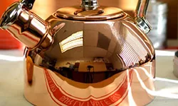
Existing sample images can confirm that copper and brass marking results are feasible directions, but final source choice, lens, pulse settings, speed, frequency, passes and acceptance criteria still need to be confirmed on the customer’s actual material and surface.
Approve the result against the production requirement
Check contrast, edge quality, appearance after cleaning, finish damage and consistency across representative parts.
Check code size, scanner distance, lighting, curvature, focus repeatability and verification grade if the project specifies one.
Check no-mark zones, coating exposure, heat effect, dimensional change and any customer-defined electrical, corrosion or wear test.
Geometry changes fixture, focus and positioning
Material response does not determine the machine configuration by itself. Flat copper busbars, small terminals, cylindrical brass collars and hex fittings can all use the same material family while requiring different holding, focusing, indexing and verification methods.
Flat plates and busbars
Start with stable support, correct field size, consistent focal height and enough edge clearance for the mark. Functional copper parts may also need defined no-mark zones.
Small terminals and connectors
Small marking areas put more emphasis on locating repeatability, character size, fixture access and contact-area control. Scanner validation may be required for compact 2D codes.
Cylindrical or curved parts
Round sleeves, collars, tubes and fittings may need rotary support or controlled indexing so the mark stays within focus and maintains the required orientation.
Hex, multi-side or mixed parts
Multi-face brass fittings and mixed small components may require indexing fixtures, recipe switching, vision positioning or operator-friendly nests rather than a single flat fixture.
| Part condition | What to evaluate | Useful route |
|---|---|---|
| Flat tags, plates or busbars | Standard marking field, fixture support, edge clearance and no-mark functional zones. | Products |
| Cylindrical tubes, collars, sleeves or round fittings | Rotary support, concentric holding, focal position and mark orientation. | Rotary & Cylindrical Marking |
| Hex or multi-side brass fittings | Indexing fixture, repeatable side positioning or multi-position loading. | Solutions |
| Small terminals or connectors | Small-character readability, fixture repeatability, contact-area control and scanner validation. | Connector and Terminal Marking |
| Randomly placed or mixed small parts | Vision positioning, locating fixture, recipe switching and operator handling. | Vision Positioning |
| Moving line or repeated batch production | Stop-and-mark, indexed conveyor, triggered online marking, data flow and downstream inspection requirements. | Flying & Online Marking |
Which laser direction should be evaluated for copper and brass?
Do not select a laser only because the material name says copper. Start with the required mark, final surface, heat sensitivity, functional restrictions and production geometry, then use sample testing to decide whether a standard fiber route is sufficient or whether more process-control range is justified.
Fiber laser marking machines are a common first evaluation route for many direct-metal identification and shallow-engraving tasks. MOPA fiber is useful when a wider pulse-control range is needed for heat input, edge quality or contrast tuning. Green-laser testing may be considered when difficult copper surfaces justify a shorter-wavelength route, while UV laser marking machines may fit selected fine-feature, coating-layer or heat-sensitive applications. None of these routes should be treated as a universal copper recipe; final selection depends on the tested part and Zhuorui’s confirmed machine configuration.
Do not start from wattage
Start from material, surface, target result and acceptance risk.
Do not promise one visual result
Contrast, depth, color and code readability remain sample-test dependent.
| Project condition | Direction to evaluate | Why it may fit | Boundary |
|---|---|---|---|
| General identification, serials, codes or shallow marks on copper/brass parts | Fiber laser | A practical first route for many direct-metal marking tasks when the final surface responds consistently. | Reflective or highly polished surfaces can narrow the process window; validate the actual part. |
| More pulse-control range is needed for heat, edge quality or contrast tuning | MOPA fiber | Wider pulse-width and frequency control provides more room to tune the process around the required result. | More tuning freedom does not guarantee a specific color, blackness, depth or durability. |
| Difficult copper surface gives a narrow or unstable process window with the initial fiber route | Green-laser testing | A shorter-wavelength route can be evaluated when improved energy coupling is useful for the specific copper task. | Confirm source availability, configuration, cost and real sample results before machine selection. |
| Fine features, selected surface layers or heat-sensitive assemblies | UV-laser testing | May be useful when localized processing and lower thermal impact are more important than a standard direct-metal route. | Use only when the mark requirement justifies it; “copper” or “brass” alone is not sufficient reason. |
| Organic coating, paint or label associated with a copper/brass component | CO2 may be relevant to the surface layer | The actual processing target may be the organic layer rather than the metal substrate. | CO2 is not the normal direct-marking choice for bare copper or bare brass metal. |
What must be checked before approving the process?
Copper and brass marking should be qualified with controlled samples and a defined acceptance method. The main risks are weak or unstable coupling, uncontrolled heat, functional surface changes and fumes or particles from coatings, oils or alloy/surface constituents.
Reflection and energy coupling
- Polished copper and brass can reflect strongly during setup.
- Oxide, brushing, polishing and surface preparation can change the response.
- Use parameter records tied to the final production surface.
Heat and functional impact
- Copper moves heat quickly; thin copper can also distort if the process is too aggressive.
- Electrical contacts, busbars and terminals may require no-mark zones or post-process functional testing.
- Deeper engraving generally increases heat input and cycle-time risk.
Finish, coating and fume control
- Brass alloy constituents, plating, lacquer, oils, paints and insulation can change the fume or particulate profile.
- Local extraction and filtration should be evaluated from the real material and surface condition.
- SDS or supplier coating information is useful when the surface chemistry is not obvious.
What to send before Zhuorui recommends a configuration
The most useful test uses the same material, surface, mark content and acceptance method as production. A convenient substitute coupon can lead to the wrong process direction.
Material
- Copper grade/type or brass alloy/grade if known.
- Surface: polished, brushed, oxidized, plated, lacquered, patinated, enamelled, oiled or cleaned.
- Thickness, part size, photos/drawings and whether the marked area is functional or cosmetic.
Mark goal
- Logo, text, serial number, QR code, Data Matrix, rating mark, scale line or artwork file.
- Target contrast, depth, line width, cell size or cosmetic finish.
- Scanner model, reading distance, verification grade or visual inspection method when required.
Production
- Batch size, loading method, fixture requirement, marking location and cycle expectation.
- Wear, cleaning, heat, corrosion, electrical, coating or assembly exposure tests.
- Fume extraction needs and SDS/coating information when available.
Copper and brass laser marking questions
Can copper and brass both be laser marked?
Yes, many copper and brass parts can be laser marked, engraved or coded. The achievable result depends on the exact grade or alloy, surface finish, coating, mark size, target depth or contrast, geometry and heat sensitivity. Sample testing is the final decision step.
Is brass the same as copper for laser marking?
No. Brass is a copper-zinc alloy. It can share some reflective-metal challenges with copper, but alloy composition, polishing, plating, lacquer and oxidation can produce a different process window and appearance. Use separate validated recipes.
Which laser is best for copper and brass?
There is no universal best source. Fiber and MOPA fiber are common directions for many direct-metal tasks. Green may be evaluated for difficult copper work where shorter-wavelength absorption is useful, and UV may fit selected fine or heat-sensitive applications. The real surface and target result decide the final configuration.
Can dark marks be made on copper or brass?
Dark or high-contrast marks can be evaluated, but blackness, tone and durability should not be guaranteed from the material name alone. Surface polish, oxide, pulse control, cleaning, alloy and viewing angle can all change the result.
Can QR codes or Data Matrix codes be marked on copper and brass parts?
They can be evaluated. Code size, cell size, surface glare, curvature, focus stability, scanner distance and verification requirement should be included in sample testing. Curved or multi-side parts may also need rotary, fixture or positioning support.
Do copper busbars, terminals or brass fittings need special setup?
Often, yes. Copper conductive parts can require no-mark zones and functional checks, while brass fittings may create curved or multi-side positioning problems. Fixture, focus, mark location and inspection method should be defined before batch approval.
Do polished, plated or lacquered parts need separate tests?
Yes. A coating, plating, polish or lacquer can become the dominant process variable. Test the final production finish rather than assuming a result from bare-metal samples.
Send the final copper or brass part and mark requirement
For copper parts, share the grade or type if known, final surface, thickness, functional contact or no-mark zones, part photos/drawings, mark artwork, target contrast or depth, code size and production requirement. For brass, also include alloy, polish, plating, lacquer or patina details when relevant. Zhuorui Laser can then evaluate the material response and recommend a practical sample-test and machine direction.