
Metal Material Marking Guide
Nickel and Nickel-Alloy Marking
Yes, nickel can be laser marked. Commercially pure nickel, nickel-based alloys and many nickel-plated surfaces can be marked for identification, traceability, codes, logos and controlled engraving. The correct process depends on whether the laser is interacting with bulk nickel, a nickel alloy or a thin nickel coating, plus the final surface finish, part geometry and required result.
- First identify bulk nickel, nickel alloy or nickel plating.
- Then define the surface condition, mark content and acceptable result.
- Use the accepted sample window to determine the final machine configuration.
Start With the Actual Nickel Surface
Can Nickel Be Laser Marked?
Yes. Nickel and many nickel-containing surfaces can be laser marked, but the material name alone is not enough to choose the process. A bulk nickel sheet, a nickel-based alloy component and a nickel-plated connector can all be described as “nickel,” while the laser is interacting with very different material structures.
Before selecting a machine, define what the laser will actually touch: bulk nickel, a nickel alloy, or a nickel coating over another substrate. Then confirm the final surface condition, target mark, allowable material removal and production requirement. This prevents a visually acceptable test from becoming unsuitable for the real production part.

Practical starting point: identify the nickel construction first, then test the final production surface. The same settings should not be assumed to work across different nickel grades, plating systems, finishes or batches.
Material Construction + Surface Condition
What Determines the Laser Marking Result on Nickel?
Two separate questions matter: what material structure is underneath, and what surface condition the laser encounters first. Both can change contrast, depth, heat tint, coating damage and repeatability.
1. Material Construction
Commercially Pure Nickel
- Includes nickel sheet, strip, foil and machined nickel components.
- Surface brightness, thickness and prior finishing can change the visible result.
- Dark contrast, light marking and shallow engraving should be confirmed on the actual grade and finish.
Nickel-Based Alloys
- Alloying elements, heat treatment and microstructure can change the laser response.
- One nickel-alloy result should not be assumed to transfer to another grade.
- Nickel content alone does not define the laser recipe.
Nickel-Plated Parts
- Plating type, layer thickness and base substrate can become process limits.
- If known, distinguish electroplated nickel from electroless nickel; they should not automatically be treated as the same marking surface.
- Thin plating may be modified or penetrated before the desired mark is reached.
- “Nickel-plated” is not a complete laser marking specification; confirm the plating process, coating thickness, base material and whether substrate exposure is allowed.
2. Final Surface Condition
Polished or Bright
- High reflectivity can make visible contrast and inspection angle more sensitive.
- Minor haze or heat tint may be unacceptable on decorative or cosmetic surfaces.
- Evaluate the mark under the real viewing and lighting conditions.
Machined, Brushed, Oxidized or Chemically Treated
- Texture and surface films can become part of the marking interaction.
- The laser may darken, lighten, disturb or partly remove the existing surface layer.
- Acceptance should include both appearance and any required functional surface behavior.
Coated, Oiled or Contaminated
- Oil, adhesive, ink, coating or residue can change both marking response and fume generation.
- A cleaned test coupon may not represent the production part.
- Test the same surface condition that will reach the production machine.
Products and Identification Needs
Where Nickel Parts Are Used and Why They Need Marking
Nickel and nickel-containing surfaces are used where corrosion resistance, heat resistance, conductivity, wear behavior or surface protection matters. Laser marking is typically added for identification, traceability, assembly control or machine-readable tracking.
Nickel and Nickel-Alloy Components
- Corrosion-resistant machined components, fittings, valves and specialty metal parts.
- Heat-resistant or chemically resistant alloy components.
- Sheet, strip, foil and formed parts that need durable identification.
Nickel-Plated Components
- Connectors, contacts, plated fasteners, housings and hardware.
- Nickel-plated steel, copper or other substrates used for protection or appearance.
- Decorative or functional plated surfaces where the coating must be considered during marking.
Why These Parts Are Marked
- Part identification and revision control.
- Lot, batch and production traceability.
- Inspection, assembly and ownership identification.
- Machine-readable tracking where codes are required.
What Is Usually Marked on Nickel?
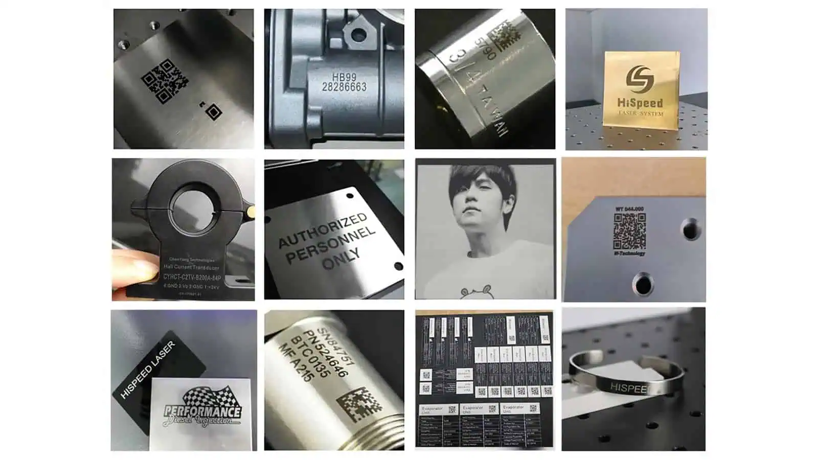
Common marking content includes serial numbers, part numbers, batch or lot codes, date codes, Data Matrix codes, QR codes, logos, polarity or identification marks, and production or inspection information. Code type is a content requirement; the laser process still has to create a surface result that remains readable on the nickel finish.
Expected Outcomes
What Marking Result Do You Need on Nickel?
Nickel marking can be tuned toward dark contrast, light or frosted contrast, shallow engraving or controlled interaction with a nickel coating. The correct result depends on the surface and on how much material change the part can accept.
| Target result | What changes on the surface | Main validation point |
|---|---|---|
| Dark contrast mark | Controlled surface heating, oxidation or microstructure change may create a darker appearance on some nickel surfaces. | Darkness, uniformity, heat tint, cleaning resistance and repeatability. |
| Light or frosted mark | Fine surface texture or micro-ablation can change reflectivity and create a lighter visual mark. | Viewing angle, surface roughness, readability and cosmetic acceptance. |
| Shallow engraving | Material is intentionally removed to create a recessed or tactile mark. | Depth, roughness, burr, heat effect, corrosion concern and whether material removal is allowed. |
| Nickel-layer modification or removal | The laser modifies or removes part of a thin nickel layer instead of marking bulk nickel. | Coating thickness, substrate exposure, edge quality, appearance and post-mark surface performance. |
For nickel-plated parts, decide this before testing: must the nickel layer remain intact, or is controlled layer modification acceptable? A visually clear mark can still be unacceptable if it exposes the substrate or compromises a required protective or cosmetic surface.
Part Geometry and Size
How Shape, Thickness and Marking Size Change the Process
The material can be suitable for laser marking while the part geometry still changes focus control, fixturing, heat input, marking field and final machine configuration.
Flat Parts
- Flat nickel sheets, plates and machined faces are the simplest geometry for focus and fixture control.
- The main variables become surface condition, mark size, field size and loading repeatability.
Curved or Cylindrical Parts
- Tubes, shafts, fittings and round connectors introduce focus variation across the surface.
- A rotary fixture may be appropriate when the mark extends around the circumference.
- Small local marks on mild curvature do not automatically require a rotary or 3D system.
Thin Nickel Foil or Thin Parts
- Heat accumulation and material removal can cause distortion, warping or excessive penetration.
- Low-mass parts should be tested for both mark quality and dimensional effect.
Thin Nickel Plating
- Coating thickness can become a hard process limit when the desired mark approaches the layer thickness.
- Contrast must be balanced against breakthrough, edge damage and substrate exposure.
Large Parts or Large Marking Areas
- Part size can determine working table size, loading access, marking field and whether repositioning or motion is required.
- A larger marking field can reduce optical detail, so field size should match the actual mark rather than simply be maximized.
Small Characters and Codes
- Small Data Matrix modules or fine characters require stable focus, suitable optics and controlled surface contrast.
- Reflective nickel surfaces can make scanner lighting and viewing angle part of the validation method.
Laser Source Direction
Fiber First, Then MOPA When the Process Needs a Wider Adjustment Window
For many bulk nickel, nickel-alloy and nickel-plated marking tasks, a fiber laser marking machine is the first machine family to evaluate. It can be tested for identification, codes, light or dark contrast and controlled material removal.
MOPA fiber becomes especially worth evaluating when the project needs a wider pulse-parameter window for contrast tuning, heat-input control, cosmetic surfaces or thin plating. MOPA does not guarantee a black mark or a plating-safe result on every nickel surface; the real sample still decides the accepted process window.
Very thin layers, adjacent heat-sensitive materials, unusually small features or special process constraints may justify evaluating another wavelength, but these are exceptions rather than the default route for most nickel marking projects.

During testing, the useful variables are not just power. Pulse behavior or pulse width when available, frequency, scan speed, hatch spacing, focus position, number of passes and overlap can shift the balance between contrast, heat tint, roughness, depth, coating damage and cycle time.
| Parameter | Typical trade-off to watch |
|---|---|
| Pulse behavior / frequency | Changes how energy is delivered over time and can shift contrast, heat accumulation and surface texture. |
| Scan speed | All else equal, slower scanning increases local energy input; faster scanning may reduce contrast or depth. |
| Hatch spacing / overlap | Tighter spacing or greater overlap can increase cumulative energy, but may also increase heat tint, roughness or coating risk. |
| Number of passes | Additional passes can increase surface change or depth, while also increasing heat and plating-breakthrough risk. |
| Focus position | Changes spot size and energy density, affecting fine detail, edge quality and material removal. |
These are process relationships, not universal nickel settings. The accepted window still has to be established on the actual production surface.
Risk Review
Common Nickel Marking Failure Modes
Most nickel marking problems come from treating different grades, finishes or coatings as if they were the same. Validation should check failure modes deliberately, not only whether one attractive sample can be produced.
Low or Angle-Dependent Contrast
- Polished, bright or inconsistent surfaces can reflect light differently.
- A mark that looks strong from one angle may look weak from another.
- Evaluate under the real lighting and viewing conditions.
Heat Tint or Cosmetic Haze
- Too much heat can change the appearance beyond the intended mark area.
- This may be unacceptable on bright, decorative or tightly controlled surfaces.
- Cosmetic acceptance should be defined before optimizing for maximum darkness.
Plating Breakthrough
- Aggressive parameters can remove too much of a thin nickel layer.
- Underlying substrate exposure can change appearance and surface performance.
- Confirm coating thickness and whether breakthrough is allowed.
Surface-Integrity or Corrosion Concern
- A visually successful mark does not automatically preserve the original protective surface.
- If nickel plating or alloy surface condition has a corrosion or functional role, the buyer’s acceptance method must be included in the test.
Roughness, Burr or Excessive Removal
- Engraving parameters can create more texture or depth than the drawing allows.
- Depth should be judged together with edge quality and any post-mark finishing requirement.
Barcode or Data Matrix Read Issues
- Reflective nickel surfaces can create scanner glare.
- Small modules need stable focus, contrast and quiet-zone control.
- Reader success is not the same as a formal verification grade.
Safety and Fume Boundary
Nickel Marking Requires Surface and Fume Review
Nickel marking is not only a visual contrast decision. Reflective metal surfaces, invisible fiber laser radiation, plating layers, oils, passivation chemistry and coatings can affect enclosure, extraction and operating procedure.
Reflection and Invisible Radiation
- Fiber laser marking commonly uses invisible near-infrared radiation.
- Bright nickel surfaces can increase reflection risk during setup.
- Open or non-enclosed marking requires controlled laser safety planning.
Fume From Surface Layers
- Nickel plating, coating, oil, ink or adhesive can change the fume profile.
- Use the actual production surface, not a cleaned substitute, for review.
- Extraction and filtration should follow material safety information and site rules.
- Nickel-containing fume or dust should be treated as an occupational exposure concern and reviewed with the buyer’s safety data, extraction method and local workplace controls.
Critical-Part Boundary
- A successful mark does not certify aerospace, medical, battery or pressure parts.
- Final acceptance must follow the buyer’s drawing, specification and validation plan.
- Zhuorui Laser can support marking feasibility and equipment configuration review.
Real-Sample Validation
Confirm the Nickel Process on the Final Production Surface
A real sample test should confirm more than whether the mark is visible. The accepted process window should match the material, final surface, geometry, marking content, appearance requirement, durability requirement and production target.
Zhuorui Laser can review the part and marking target, test a suitable laser direction, compare the result against the buyer’s acceptance criteria, and then use the accepted sample window to define the machine configuration.
For production work, repeat the accepted condition on more than one representative part when plating thickness, surface finish, cleaning state or batch condition can vary. One good-looking sample does not demonstrate production consistency.
Nickel Sample Validation Checklist
- Material identity: commercially pure nickel, nickel-based alloy, nickel plating, base substrate and grade if known.
- Surface condition: polished, brushed, machined, oxidized, chemically treated, coated, oiled or production-cleaned.
- Part geometry: dimensions, marking area, flatness, curvature, thickness and fixture constraints.
- Marking content: serial number, part number, logo, QR code, Data Matrix, lot code or other identification.
- Target result: dark contrast, light/frosted mark, shallow engraving or controlled coating interaction.
- Acceptance method: visual inspection, scanner reading, verification grade if required, cleaning or abrasion test, allowable depth, coating breakthrough limit, cosmetic limit or corrosion requirement.
- Production requirement: batch size, target cycle time, loading method, repeatability, automation need and destination-market requirements.
From Test Result to Equipment
How the Sample Result Defines the Final Machine Configuration
The final machine should be configured from the accepted marking window, not from the word “nickel” alone. Once the result is approved, the optical, mechanical, safety and production requirements can be converted into an equipment specification and quotation.
Laser Source and Power Class
- Choose fiber or MOPA from the accepted sample result and required adjustment range.
- Power class should support the required contrast, depth and throughput without unnecessary heat or coating damage.
Lens and Marking Field
- Field size should match the actual marking area, character size and code-module requirement.
- A larger field is not automatically better if it sacrifices optical detail needed by the mark.
Fixture and Rotary
- Flat or irregular parts may need a repeatable locating fixture.
- Cylindrical parts may require a rotary fixture when the marking area extends around the circumference.
Enclosure and Extraction
- Machine structure and safety configuration should match the loading method and operating environment.
- Extraction should be reviewed for plated, coated, oily or contaminated surfaces and the buyer’s site requirements.
Automation and Data
- Barcode input, serial generation, PLC/MES communication, trigger control or conveyor integration are project requirements, not automatic features of the material route.
- Confirm these only when the production process actually needs them.
Information Needed for Quotation
- Material and plating details, final surface condition and part photos or drawings.
- Marking file, mark size, target result and acceptance requirement.
- Batch size, cycle expectation, fixture or automation need, destination voltage and safety requirements.
Configuration sequence: material + surface → part geometry → marking content → target result → accepted sample window → laser source and optics → fixture/safety/extraction → automation requirement → quotation.
FAQ
Common Questions About Nickel and Nickel-Alloy Marking
Can nickel be laser marked?
Yes. Commercially pure nickel, many nickel-based alloys and many nickel-plated surfaces can be evaluated for laser marking. The final result depends on the material construction, surface finish, target mark and allowable material change.
Does nickel always produce a black laser mark?
No. Dark contrast may be achievable on some nickel surfaces, but the result varies with alloy, finish, plating, heat response and parameter window. Blackness should be treated as a sample-validation target rather than a guaranteed material property.
Is MOPA required for nickel?
Not automatically. Standard fiber is a common first evaluation route. MOPA becomes useful when a wider pulse-control window is needed for contrast tuning, heat control, cosmetic surfaces or thin plating.
Can nickel-plated parts be marked without damaging the plating?
Sometimes, but the result depends on plating type, coating thickness, base substrate, target contrast and allowable material removal. Thin plating must be tested specifically for breakthrough and surface-integrity requirements.
Can QR codes or Data Matrix codes be marked on nickel?
They can be evaluated, but reflective surfaces, code size, quiet zone, scanner lighting, curvature and focus stability must be checked. Reader success should not be confused with a formal verification grade when a grade is required.
What should I send for quotation?
Send the nickel grade or plating details if known, final surface condition, part photos or drawings, marking file, mark size, target effect, acceptance method, batch size, cycle requirement and any fixture, safety or automation requirement. Use Request a Quote for equipment pricing or Contact Us for sample-testing questions.
Next Steps
Validate the Nickel Sample, Then Configure the Machine
Send the material or plating details, final surface condition, part geometry, marking content and acceptance requirement. Zhuorui Laser can review the sample first, establish a suitable process direction, and then recommend the laser source, optics, fixture, safety and production configuration needed for quotation.
Prepare for faster evaluation: nickel grade or plating details · final surface condition · part photos or drawings · shape and dimensions · marking content and size · target contrast or depth · scanner or durability requirement · batch size · cycle expectation · fixture, extraction or automation needs.