
Anodized Aluminum Laser Marking
Yes. Anodized aluminum can usually be laser marked, but the accepted result depends on the alloy, anodizing type, color, sealing, surface texture, part geometry and the mark you need. The first decision is not simply whether a laser can make a visible mark, but whether it can produce the required contrast, durability and repeatability without unacceptable damage to the anodized surface or the aluminum beneath.
Request a Sample Test Discuss Anodized PartsCan Anodized Aluminum Be Laser Marked?
Yes. Anodized aluminum is commonly suitable for laser marking, but the useful process window is controlled by the anodized surface system and the required result. A visible mark is only the starting point; production approval should also consider consistency, readability, durability and whether the process changes the protective anodized layer more than the application allows.
Light or white contrast
A light-looking mark can come from modification within the anodized surface, partial removal of the colored layer, or exposure of lighter aluminum beneath. The sample test should confirm which interaction is producing the accepted appearance.
Dark or tone-shift contrast
Darker results can be possible on selected anodized surfaces, but the shade depends on the anodizing system, alloy and pulse conditions. Do not treat “black” as a guaranteed result without a color-matched trial.
Production consistency
Part-to-part shade, gloss, brushing direction, layer condition and anodizing batch can change perceived contrast. Approval should use an agreed reference, inspection lighting and production-matched samples.
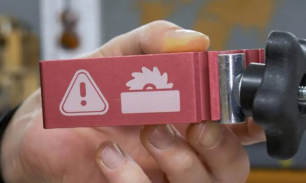
Identify the Anodized Surface Before Choosing Parameters
“Anodized aluminum” is a surface system. The alloy, anodizing type, dye, sealing, texture and post-process all influence absorption and the usable process window.
Confirm the production surface, not only the color name
The reference images below help explain the variables to inspect, but anodizing color alone does not identify alloy, anodizing type, layer thickness, sealing or laser response. Use production-matched parts or coupons for the final process decision.
Color and dye
Black, red, blue, gold and natural anodizing can produce different contrast and heat response. Test each production color rather than extrapolating from a single swatch.
Layer and sealing
Anodic thickness, pore sealing and hard-anodize treatment change how readily the layer clears and how durable the mark remains.
Texture and gloss
Brushing lines, bead blast, machining marks and polished areas change perceived white contrast and can expose non-uniformity after marking.
Part and post-process
Masking, cleaning, clear coats, assembly and wear exposure can change the accepted appearance. Send the part as it will arrive at production.
Where Are Anodized Aluminum Parts Used and Why Are They Marked?
Anodized aluminum is common where a lightweight metal part also needs corrosion resistance, a controlled finish or a durable decorative surface. Laser marking is used when identification, traceability or branding must be added without labels, ink or separate plates.
Electronics housings and panels
Mark model identifiers, serials, ports, control labels, safety information or branding while keeping the finished metal appearance.
Industrial nameplates and instruments
Add permanent part numbers, scales, asset IDs, operating labels or machine information that must remain legible through handling and cleaning.
Mechanical and transport components
Use serials, batch codes, supplier IDs or assembly references for traceability where anodizing is already part of the surface-protection process.
Consumer and premium metal parts
Create logos, product identifiers and decorative marks where contrast, edge quality and visual consistency matter as much as basic readability.
What Is Usually Marked on Anodized Aluminum?
The marking content determines feature size, verification requirements and how much visual consistency matters. Define the smallest real feature and the actual data format before the sample test.
Logos and branding
Appearance is usually the priority. Evaluate edge sharpness, fill uniformity, contrast and consistency across the approved anodizing colors.
Part numbers and serial numbers
Legibility and repeatability matter more than a single attractive sample. Confirm the smallest text height and the production data source.
QR and Data Matrix codes
Cell definition, quiet zone, contrast and verifier performance should be checked at the real code size rather than judged only by eye.
Labels, symbols and scales
Control panels, instruments and housings may need icons, port labels, scales or functional markings that must remain readable after cleaning and handling.
What Marking Result Are You Trying to Achieve?
Define the visual and functional acceptance target before choosing parameters. A similar-looking mark can be produced by different interactions with the anodized surface, so appearance alone should not be used to assume whether the oxide layer was modified, partially removed or fully penetrated.
| Target result | Physical effect to verify | Acceptance checks |
|---|---|---|
| White or light mark | Surface color change, modification within the anodized layer, partial layer removal or substrate exposure may all produce a light appearance depending on the surface system | Contrast, edge quality, actual layer condition, wear resistance and whether corrosion protection remains acceptable |
| Dark or tone-shift mark | Controlled color or surface modification within the usable thermal and pulse window | Shade repeatability, heat halo, code readability and no unacceptable distortion or surface damage |
| Color-consistent logo or code | Repeatable interaction across the same color, texture, layer stack and supplier batch | Delta from approved reference, batch variation, scan direction and inspection method |
| Fine 2D code or serial | Feature formation in or through the anodized surface while maintaining cell definition | Cell size, quiet zone, verifier result, focus repeatability and cycle time |
| Deeper engraving | Intentional removal beyond the anodized layer into the aluminum substrate | Depth, burr, roughness, corrosion exposure, structural limits and downstream cleaning requirements |
How Do Part Shape, Thickness and Size Change the Process?
The same anodized surface can need a different machine setup when the part becomes curved, thin, recessed or larger than the marking field. Geometry affects focus, heat accumulation, beam access, fixturing and how the part must be positioned.
Flat plates and panels
Flat parts are usually the simplest to fixture. Check flatness, consistent working distance and whether the complete mark fits inside the required field without repositioning.
Cylindrical or curved parts
Curvature changes focus across the mark. Circumferential work may need a rotary axis; more complex height changes may require a different focusing or positioning strategy.
Thin-wall parts
Low thermal mass can make local heating, distortion or gloss change more visible. Fixturing, pulse conditions, scan strategy and total heat input become more important.
Large or stepped parts
Large housings may exceed a single marking field, while recesses and height steps can move the surface out of focus. Field size, part datum, beam access and repositioning repeatability must be included in the machine decision.
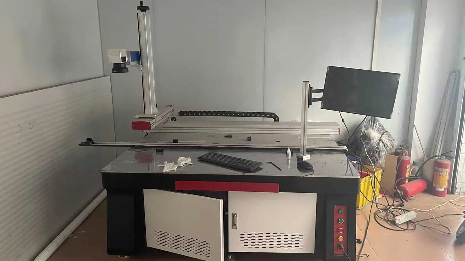
Which Laser Route Is Worth Testing?
Fiber and MOPA fiber sources are common starting points for anodized aluminum because they can support controlled surface modification, selective removal and contrast formation. The right choice still depends on color, coating thickness, mark width, heat sensitivity and cycle target.
Use fiber laser marking machines as the initial route for many parts. Consider MOPA when pulse-width control may widen the contrast window. UV is a selective option for fine features or heat-sensitive assemblies, and should be justified by samples.
| Source | Potential fit | Boundary |
|---|---|---|
| Fiber, around 1064 nm | Surface modification, selective removal, contrast formation, logos, serials and many 2D codes | White contrast and heat effect vary with dye, sealing and alloy. |
| MOPA fiber | Pulse tuning for shade control, fine detail or lower heat input | More control does not remove the need for a color-matched sample test. |
| UV, often 355 nm | Selected fine-feature or heat-sensitive jobs | Evaluate cost, throughput and actual contrast before selecting. |
| CO2 | Some organic overlays or non-metal components in an assembly | Not the normal first route for direct anodized aluminum marking. |
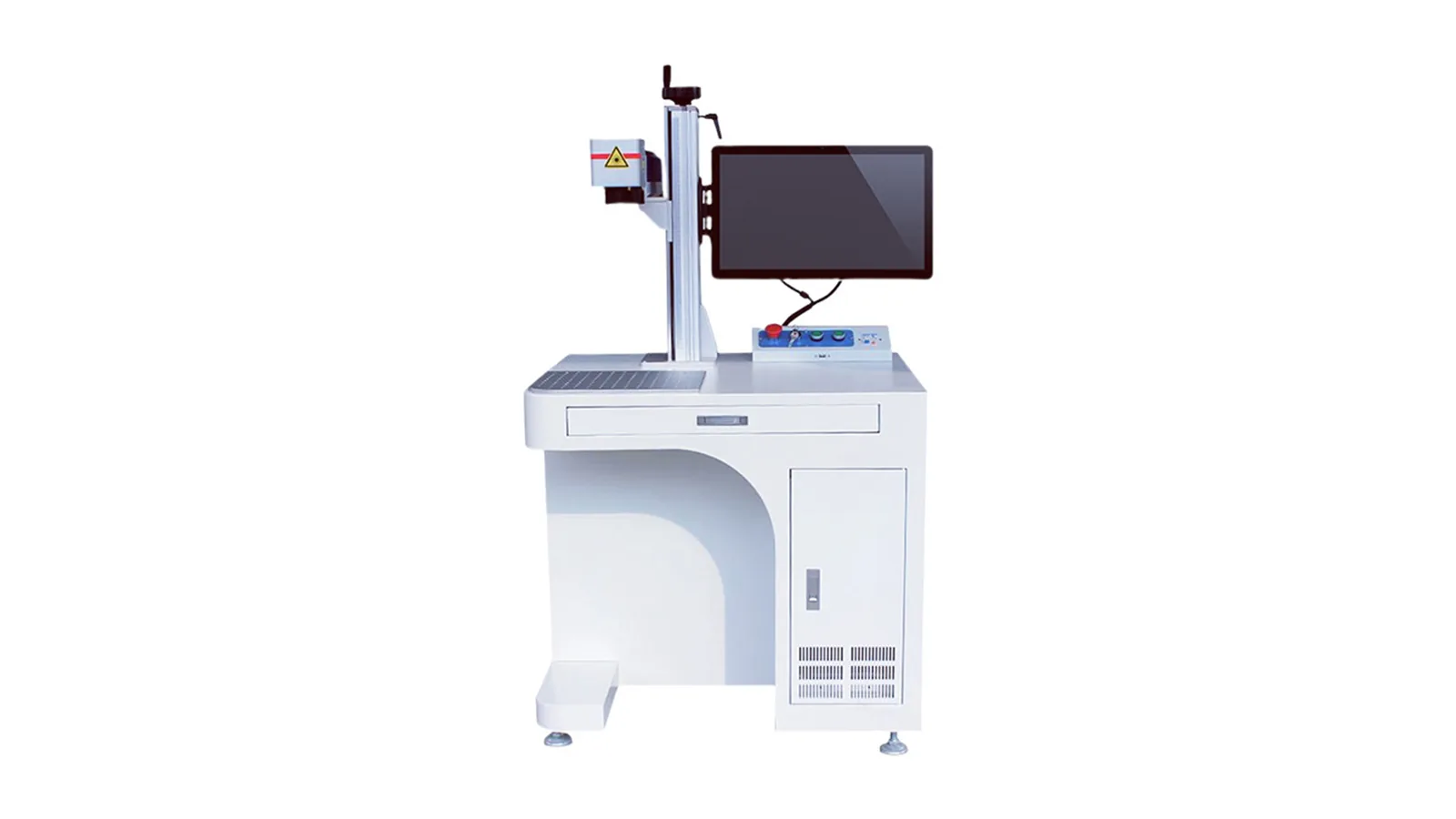
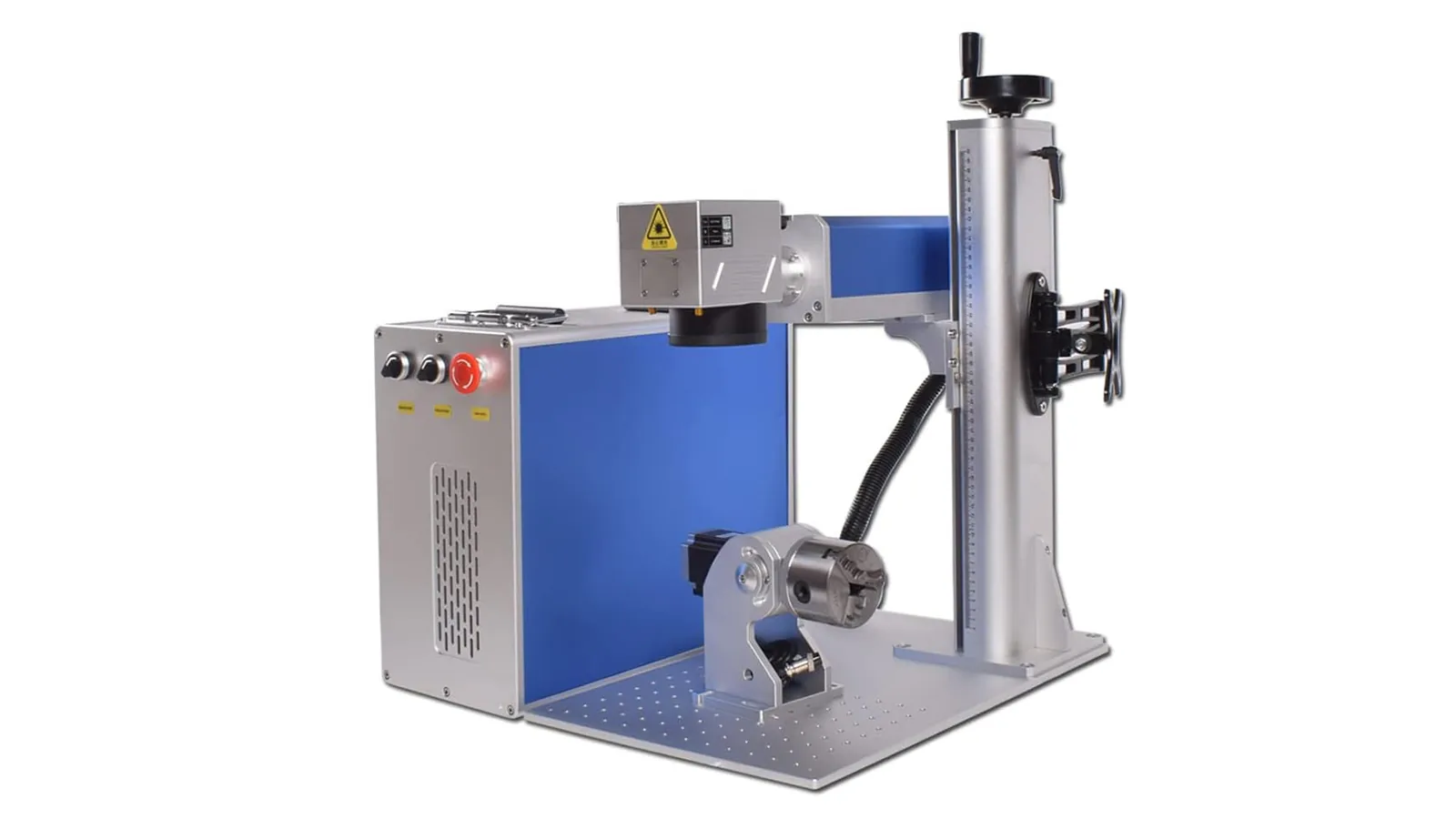
What Are the Common Risks and Failure Modes?
Most failures are not simply “too much power” or “too little power.” They often come from the interaction between surface variation, focus, thermal input, scan strategy and the acceptance target. Diagnose the visible symptom first, then check the variables most likely to cause it.
| Failure | Common contributing factors | What to check next |
|---|---|---|
| Weak, gray or inconsistent contrast | Anodizing color or batch variation, sealing, insufficient or unstable process window, focus variation | Compare production-matched batches, focus position and neighboring parameter windows. |
| Edge haze, banding or gloss change | Excess local heat, hatch strategy, scan direction, brushing direction or pass overlap | Review pulse conditions, speed, hatch spacing, pass order and the surface texture direction. |
| Unexpected substrate exposure | Excessive removal, thin anodic layer or repeated passes | Confirm whether the accepted result allows oxide removal and whether corrosion protection remains adequate. |
| Poor QR or Data Matrix verification | Feature size, low contrast, focus error, cell deformation or inconsistent background | Check the real code size with a verifier and adjust focus, cell geometry and process margin. |
| Part distortion or heat halo | Thin-wall geometry, thermal accumulation, poor heat sinking or excessive dwell | Review fixture support, scan sequence, pulse conditions and total local heat input. |
| Loss of contrast after cleaning or wear | Surface interaction is not durable enough for the downstream environment | Repeat the required abrasion, solvent, sweat, UV, heat or cleaning test on the approved production surface. |
Build a Parameter Window, Not a Single Setting
A useful feasibility test varies one controlled group of parameters at a time and records both appearance and functional effects. Values should be developed on the actual machine, lens, alloy and anodized batch rather than copied from an unrelated sample.
| Variable group | What to compare | What to record |
|---|---|---|
| Laser source and pulse | Source type, pulse width where adjustable, frequency and pulse energy | Light/dark response, heat halo, edge quality and usable process margin |
| Energy delivery | Average power, scan speed, pass count and hatch spacing | Surface change, substrate exposure, cycle time and repeatability |
| Beam and focus | Lens/field, spot size, focal position and part height variation | Minimum feature, edge width, code quality and focus tolerance |
| Scan strategy | Fill direction, cross-hatch, contour passes and marking order | Banding, brush-direction interaction, corners and visual uniformity |
| Surface batch | Each alloy, anodizing color, thickness, sealing and supplier batch | Part-to-part variation against an approved reference under controlled lighting |
Keep the approval record with the approved sample
Record the parameter revision, machine and lens, material and anodizing batch, inspection lighting, reader or verifier setup, durability result and any evidence of substrate exposure. This makes the accepted result reproducible instead of relying on a single visual sample.
Sample-Test Checklist for Anodized Aluminum
A production approval needs the same alloy, anodizing color, layer condition and post-process as the final part. Photos or bare coupons are useful for discussion but cannot prove color consistency.
| Input | Provide | Check |
|---|---|---|
| Surface | Alloy, anodizing type, dye/color code, thickness, sealing and texture | Sample matches production supplier and batch conditions. |
| Artwork | Logo, text, serial, QR/Data Matrix, smallest feature and mark location | Readability and edge quality at the real size. |
| Target appearance | White, dark, tone-shift or color-matched result with reference images | Visual delta under agreed lighting and viewing angle. |
| Durability | Abrasion, solvent, sweat, UV, heat, corrosion or assembly exposure | Mark remains within the acceptance window after testing. |
| Production | Cycle time, loading, focus variation, fixture and data source | Full cell cycle and repeatability, not scan speed alone. |
| Safety | Coating SDS, cleaning agents, extraction and enclosure constraints | Guarding and fume controls fit the complete setup. |
Send the final anodized part
Include representative parts or coupons from each production color. If a clear coat, masking, assembly or cleaning step follows marking, include that sequence in the validation plan.
How Is the Final Machine Configuration Chosen?
The material name alone does not determine the machine. The final configuration should follow the approved sample result and the way the real part must be positioned, marked, verified and handled in production.
| Production input | Configuration consequence |
|---|---|
| Required contrast and approved process window | Confirms whether standard fiber, MOPA fiber or another tested source route is the better starting configuration. |
| Mark size and smallest feature | Drives lens and field-size selection, with a trade-off between coverage, spot size, focus tolerance and required detail. |
| Flat, cylindrical, curved or height-varying part | Determines whether a flat fixture is enough or whether rotary positioning, additional axes, height control or a different focusing strategy should be evaluated. |
| Part-to-part position variation | May require stronger fixturing, datum control or vision-assisted positioning when manual placement cannot hold the required repeatability. |
| Static artwork versus variable data | Defines the controller, software and data-input requirements for serial numbers, codes or production database integration. |
| Cycle time and loading method | Determines whether a manual workstation is sufficient or whether faster handling, indexing, conveyor or project-based automation should be evaluated. |
| Operator access, reflection and fumes | Drives enclosure, interlock, extraction and fixture decisions for the complete system rather than the laser source alone. |
What to include in an RFQ
Send the production part or representative samples, alloy and anodizing information, artwork or code, target appearance, mark size and location, expected cycle time, loading method, annual or batch volume, data requirements, durability criteria and any enclosure or extraction constraints. The sample result can then be translated into a machine, lens, fixture and handling configuration.
Laser Radiation, Reflection and Fume Controls
The sample result does not define the safety class of the complete machine. Safety evaluation must cover the source wavelength, enclosure, access points, fixtures, extraction and the way the operator loads or services the system.
Invisible laser radiation
Fiber and MOPA systems commonly use invisible near-infrared radiation. Direct exposure and specular or diffuse reflections from aluminum must be controlled through the complete optical and mechanical design.
Enclosure and access
An enclosed workstation should be reviewed for interlocks, viewing window suitability, emergency stop behavior and openings created by custom fixtures. An enclosure alone does not prove a final Class 1 system.
Open or automated cells
Open setups may require a controlled laser area and trained operators. Automated cells also need a defined safe state for access, faults, jam clearing, maintenance and loss of extraction.
Fumes and surface residues
Review anodizing dyes, sealants, clear coats, oils, cleaners and adhesives using supplier information or SDS. Local extraction and filtration should be selected for the actual surface stack and removal rate.
Fixture orientation
Part angle, polished edges and reflective fixtures can redirect energy. Validate workholding, beam stops and focus controls for every production orientation.
Deep marking boundary
If marking continues into the aluminum substrate, assess depth, structural section, fatigue, corrosion protection and downstream finishing rather than approving appearance alone.
Anodized Aluminum Laser Marking FAQs
Can a laser remove the anodized layer without cutting deeply into aluminum?
Often yes, when energy is controlled for the layer thickness and the required contrast. Removal depth, edge haze and substrate exposure still need verification on the final color and alloy.
Is a white mark guaranteed on black anodized aluminum?
No. Black anodizing often provides a strong starting contrast, but dye, sealing, texture and process variation can change the result. Approve against a reference sample.
Can anodized aluminum be laser marked in black?
Darker or tone-shift marks may be possible on selected surfaces, but they are process-dependent and should not be promised without a color-matched test.
Which laser is commonly evaluated first?
Fiber or MOPA fiber is a common starting direction for anodized aluminum. UV can be considered for selected fine-feature or heat-sensitive work when the sample result supports it.
Does a white-looking mark always mean the anodized layer has been removed?
No. A light appearance can come from different interactions with the anodized surface. The sample test should confirm whether the layer was modified, partially removed or penetrated to the aluminum beneath, especially when corrosion protection or wear performance matters.
What should I send for a sample test?
Send the final anodized color and alloy, layer information, artwork, target appearance, durability criteria, cycle target and any SDS or safety constraints.
Send the Final Anodized Surface and Mark Requirement
Include the alloy, anodizing color and thickness, artwork or code, target appearance, mark size and position, part dimensions and geometry, cycle expectation, loading method, durability criteria and safety constraints. Zhuorui Laser can use the sample result to evaluate the laser route, lens, fixture, handling method and machine configuration for the next quotation step.
Request a QuoteOEM & Custom InquiryContact Us