
Charger and Power Adapter Laser Marking
Nameplate, certification and traceability marking for charger and power adapter housings — rating information, model and serial numbers, date codes and brand marks produced without ink, pads or other marking consumables.
This page covers the industry-task view for selecting a charger laser marking machine: why these products are marked, what gets marked, which material and surface conditions control the result, what result to target, how the housing should be positioned, which laser direction to test first, what can fail in production, and how sample-test results determine the final machine configuration.
Charger and Power Adapter Laser Marking at a Glance
Yes — laser marking is an established method for adding durable identification to charger and power adapter housings. In power-product manufacturing, plastic and aluminum housings can carry rating information, certification and warning symbols, brand marks, model numbers, serial numbers and date or lot codes. The achievable contrast and appearance depend on the actual material, color and surface finish. The practical question is not whether a charger housing can be marked, but what must be marked, what result is acceptable, which material and geometry variables control that result, how the part will be positioned in production, and which laser direction should be sample-tested first.
Material behaviour — why ABS and polycarbonate grades, black and white housings, and coated or anodized surfaces respond differently — belongs to the dedicated material pages linked throughout, not to this page. If your question is about PCB marking or cable and wire marking inside or alongside the charger, those are separate application pages under the same Electronics & Electrical section.
Why Are Chargers and Power Adapters Marked?
The marking job is not only cosmetic branding. It usually combines product identification, rating or compliance-related information, and production traceability — with the exact required content defined by the product design and the applicable market or certification requirements.
Product information and identification
Charger and adapter housings commonly need visible model information, electrical ratings, warnings, certification symbols and brand identification. The laser process can be evaluated as a way to create this content without relying on a surface-applied ink layer, while the required wording, symbols and marking method remain subject to the applicable product and market requirements.
Traceability and verification
Serial numbers, date or lot codes and machine-readable symbols can connect an individual unit to production, quality or verification records. When the content changes per unit, the marking task also becomes a data-handling and verification problem: the correct value must reach the marker, be placed in the correct zone and, where required, be read back before the part is released.
What Chargers and Power Adapters Typically Get Laser Marked
Once the marking purpose is clear, define the physical parts and the exact content that need to be marked. Charger and adapter projects commonly involve molded plastic housings, aluminum housings and selected plug or assembly components, with different mark content on each surface.
Rating plates and certification info
The most recognizable mark on any charger or adapter is its rating plate — input voltage and current, output voltage and current, power rating, model number, and the certification and warning symbols required for the target market. On molded plastic housings this content may otherwise be printed or molded; laser marking avoids reliance on a surface-applied ink layer, while final legibility and durability still need to be verified on the actual housing. What the plate must contain, and whether laser marking is acceptable as the marking method for a given certification scheme, is defined by the certification bodies and the target-market regulations — not by the laser process.
Brand, model and traceability codes
Brand logos and model markings are marked on the most visible face of the housing for identity. Serial numbers, date codes (commonly year-week formats), lot codes and QR or Data Matrix symbols are marked for traceability — and increasingly for anti-counterfeiting, where a code on the housing links the unit to a verification record. When the code value is generated per unit by a database or MES and must be verified after marking, the data-flow design belongs to the traceability and data integration solution rather than to this application page.
Typical parts in scope
The most common workpieces on this page are molded plastic charger or adapter housings, aluminum adapter housings, and selected interchangeable-plug or travel-adapter components. The exact housing material and finish still matter later in the decision path, because ABS / PC blends, different colors, bare aluminum, anodized aluminum and coated surfaces do not produce the same marking response.
| Part family | Typical mark content | Typical location |
|---|---|---|
| Plastic housing (ABS / PC blend) | Rating plate, certification and warning symbols, brand logo, model, serial, date code, QR / Data Matrix | Main face or bottom face — must stay readable to the end user |
| Aluminum housing (bare, anodized or coated) | Rating plate, brand logo, model, serial, date code | Flat band on the main face or bottom |
| Interchangeable-plug / travel-adapter components | Part ID, lot code, assembly mark | Flat internal or edge face, per product design |
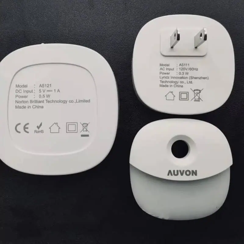
Rating Plate and Identification Marks on Charger Housings
Charger housings commonly carry model information, electrical ratings, certification symbols and other identification content on an outward-facing surface. Laser marking can be evaluated when a permanent, consumable-free marking process is required.
Engineering takeaway: the rating plate must sit on an outward, readable face — that is the working rule for chargers, opposite to parts marked in hidden zones.
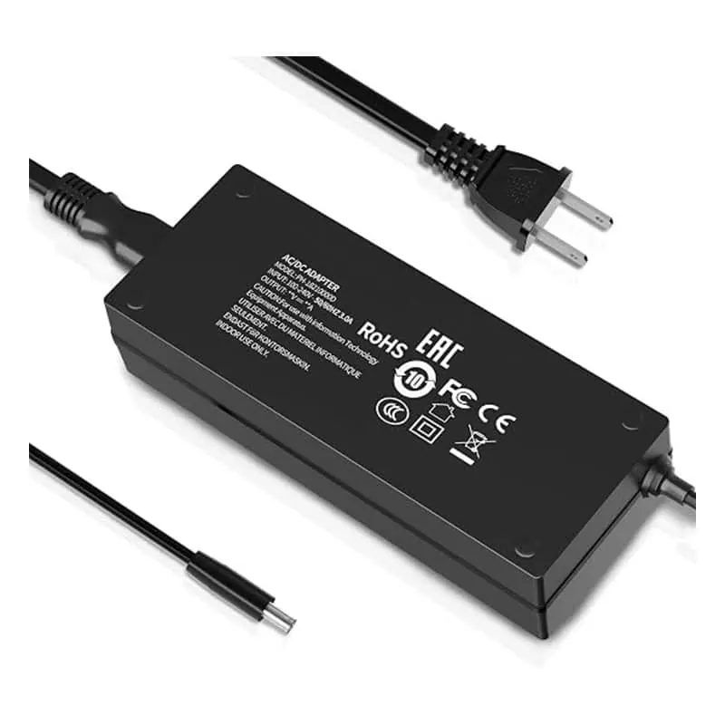
Rating and Identification Marks on a Power Adapter Housing
A power adapter housing can carry model, electrical ratings, certification symbols and other identification information on a flat exterior face. Final laser contrast and durability should be confirmed on the actual housing material and surface.
Engineering takeaway: housing material, color, surface coating and target contrast all affect the laser result, so the actual adapter should be sample-tested before the process is finalized.
What Determines Laser Marking Results on Chargers and Power Adapters?
The housing material name alone is not enough to select the process. The result is controlled by the combination of material formulation, color and finish, mark size and content, surface geometry, part presentation and the acceptance criteria the finished mark must meet.
Material, color and surface condition
ABS, polycarbonate and flame-retardant blends can respond differently even when the parts look similar. Colorants, additives and surface texture can change contrast and the usable parameter window. Aluminum also needs to be separated by surface state — bare, anodized, painted or otherwise coated — because the layer on the surface changes how the mark forms. The actual production-grade housing is therefore more useful for testing than a generic flat coupon.
Mark size, code density and available area
Small rating text, serial numbers and QR or Data Matrix symbols place different demands on the optical setup. The smallest character, the code cell size, the total marking area and the available solid land on the housing all affect the field size and process window that should be evaluated. When a fixed scanner will read the code, position tolerance becomes part of the result requirement rather than a separate afterthought.
| Variable | Why it changes the result | What to confirm for testing |
|---|---|---|
| Housing material / formulation | Different resins, blends and additives can produce different contrast and thermal response | Actual production housing; grade or formulation information if available |
| Color | Dark, light and brand-colored housings can require different contrast targets and parameter windows | Representative production colors |
| Surface finish / coating | Texture, paint, anodizing or other layers change how the mark forms | Finished surface, not only the base material |
| Mark content and smallest feature | Fine text and dense codes can narrow the usable optical and process window | Final artwork, character size, code size and marking area |
| Geometry and height variation | Curvature and part-height variation affect focus and edge quality | Complete part, drawing and marked-face geometry |
| Loading and positioning | Fixture or presentation repeatability affects where the mark lands | Tray, fixture, random placement or inline presentation method |
| Acceptance target | The process window is only meaningful when contrast, code, durability and position limits are defined | Pass / fail criteria for the finished mark |
What Marking Result Should You Target?
Before choosing the machine, define what a passing mark looks like. A visually acceptable logo, a small rating plate and a machine-readable traceability code can require different acceptance criteria even on the same housing.
Visual and code result
- Contrast and legibility — text must be readable on the actual housing color under the intended inspection conditions.
- Character and edge quality — small rating text should remain sharp enough for the drawing or brand requirement.
- Code readability — QR or Data Matrix symbols should be tested with the intended reader or verifier.
- Position — the mark must stay inside the allowed zone and within any scanner or cosmetic position tolerance.
Surface, functional and durability result
- Surface appearance — avoid unacceptable burning, yellowing, melting, roughness or uneven coating removal.
- Housing integrity — the process must not create unacceptable damage to thin walls, seams, ports or other functional zones.
- Durability — define the required rub, wipe, humidity, sweat, cleaning-agent or temperature exposure checks for the application.
- Consistency — the accepted effect should remain repeatable across the intended production presentation and representative housing batches.
A useful sample-test brief therefore describes the result in measurable or inspectable terms — not only “mark this charger housing,” but the required content, size, contrast direction, code-read requirement, allowed mark zone, surface limits, durability checks and production cycle target.
Where the Mark Goes: Readable Faces vs Keep-Out Zones
Position is a design decision as much as a laser decision. Where the applicable product standard, certification scheme or product design requires identification to remain externally accessible, the required nameplate or certification information should be placed on a designated readable face — while ports, pins, vents and seams stay clear.
Readable exterior faces
For identification that the applicable standard, certification scheme or product design requires to remain externally readable, the main face or bottom face is a common target. The exact location should follow the product’s marking and inspection requirements; traceability codes can be placed wherever the design allows, often beside the rating block or on the bottom face near the model text. On aluminum adapters, a flat band along the body or the bottom face usually provides a more stable marking surface.
Keep-out zones
- Ports and pins — USB, DC and mains contacts are functional surfaces; marking near them risks the connector zone and serves no legibility purpose.
- Ventilation slots and holes — interrupting the beam across a slot produces broken characters; the mark must fit a solid land area.
- Assembly seams and snap lines — the joint area carries mechanical function and cosmetic alignment.
- Curved edge transitions — sharp curvature defocuses the beam and distorts characters; if the only solid area is curved, a 3D or small-field approach enters the evaluation.
Geometry, Fixturing and Positioning
Chargers and adapters are small, mostly flat or gently curved housings produced in very large numbers. The geometry question is less about reachability than about presenting many small parts to the beam accurately and repeatably.
Flat housings and tray marking
A flat-faced housing in a dedicated tray is the simplest case: the tray positions many units in one field, and the machine marks them in one or several passes. Fixture repeatability — not the laser — is usually what limits position accuracy in tray marking, so the tray design and the housing tolerance deserve as much attention as the marking parameters.
Slightly curved housings
Gentle curvature across the mark zone shortens the usable depth of focus: characters at the edge of a curved area can go soft while the center stays sharp. Whether the curve fits within the focus tolerance is a sample-and-calculation question; when it does not, a 3D dynamic-focus marking approach or a smaller field with repositioning enters the evaluation.
Random placement and vision positioning
When housings arrive in random positions — on a feeder, in loose trays, or handled by operators — vision positioning locates each part and corrects the mark position automatically. The vision approach and its integration with the marking cycle are covered by the vision positioning solution; the vision CCD machine family is the matching product direction.
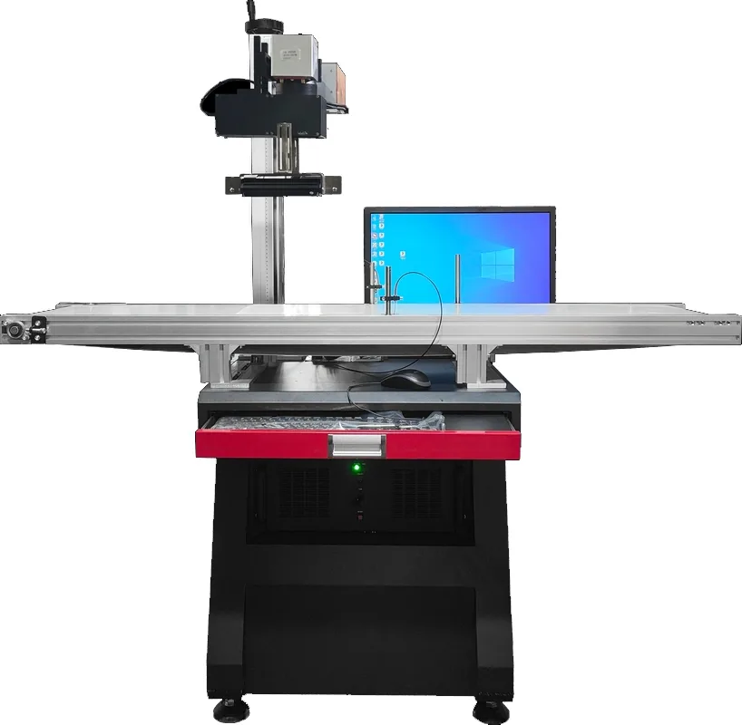
Vision-guided marking can reduce dependence on precision X/Y locating fixtures when part height, presentation and focus remain controlled. The camera locates each housing and corrects position and rotation within the field before the laser fires at the intended spot. This is useful for flexible or mixed-part charger marking when tray positions are not repeatable, and for serialized codes that must stay within a reader’s position tolerance. Vision does not by itself correct uncontrolled height, focus or part stability.
Engineering takeaway: vision can compensate for X/Y position and rotation, but the workstation still has to control part height, focus and stability. Use vision when lateral placement is not repeatable; do not treat it as a substitute for every fixture requirement.
| Part geometry | Typical fixturing | Configuration direction |
|---|---|---|
| Flat housing face, high density | Dedicated multi-cavity tray | Standard desktop or split machine, tray batch |
| Slightly curved face | Tray or cradle presenting the tangent plane | Depth-of-focus check on sample; 3D if the curve exceeds tolerance |
| Bottom face only (rating plate) | Flip fixture or two-station presentation | Indexing tray / second setup |
| Random placement | Vision-guided positioning | Vision CCD machine / vision solution |
Which Laser Direction to Evaluate First
Charger housings split cleanly by material, so the starting direction follows the housing you are marking — and the final choice depends on the housing color, the target contrast and sample results.
Plastic housings: ABS and PC
For molded ABS and polycarbonate housings, UV lasers (around 355 nm) are often the first direction to evaluate: the short wavelength and low heat input support fine, clean text on both dark and light plastics with a lower risk of burn marks on thin walls. Fiber lasers (1064 nm) also mark some plastic formulations, but the outcome is resin- and color-specific — flame-retardant additives, colorants and surface texture all change the result, which is why the realistic contrast belongs to the plastics material pages rather than to a general rule here.
Aluminum housings
For aluminum adapter housings, a Q-switched fiber laser (about 1064 nm) is often the first direction to evaluate. The final contrast and appearance on bare aluminum depend on the alloy, surface condition and parameter window, so the actual mark should be confirmed on the housing sample. Anodized and coated housings behave differently — the layer changes how the mark forms — and those cases are covered on the anodized aluminum and coated surface material pages.
When contrast goals change the choice
If the goal is a light mark on a dark housing, a dark mark on a light housing, or a coating-removal effect, the direction and the parameter window can change. These targets are material- and color-specific, and the right way to decide is a sample test on the actual housing — not a general rule.
| Housing material / surface | Starting direction | Material page for detail |
|---|---|---|
| ABS / PC housing, dark or light | UV (355 nm) often first | ABS / Polycarbonate |
| Flame-retardant plastic blend | UV often first; resin-specific | Plastics & Polymers |
| Bare aluminum housing | Q-switched fiber (1064 nm) | Aluminum |
| Anodized aluminum housing | Fiber / MOPA, layer-specific | Anodized Aluminum |
| Coated plastic housing | Coating-removal or contrast-change evaluation on sample | Coated Plastic |
| Painted or coated aluminum housing | Coating-removal or layer-specific fiber evaluation on sample | Painted Metal |
What Common Charger and Adapter Marking Failures Should the Sample Test Catch?
A sample test is most useful when it is designed to expose failure modes before the workstation is finalized. The problem is not only whether one sample can be marked, but whether the result remains readable, correctly positioned and production-safe across the intended part and process window.
| Failure mode | Typical driver to investigate | What the test should decide |
|---|---|---|
| Contrast is weak or inconsistent | Housing formulation, color, additives, coating or parameter window | Whether the current laser direction and parameter window are suitable on the real housing |
| Plastic yellows, burns, melts or becomes rough | Excessive thermal load for the housing and target effect | Whether a lower-heat process window or a different laser direction should be evaluated |
| Small text becomes soft or distorted | Feature size, focus, field choice, curvature or height variation | Whether optics, field size, fixturing or 3D focus control needs to change |
| QR / Data Matrix reads inconsistently | Contrast, symbol size, surface texture, focus or position variation | Whether code size, process settings, fixture or vision positioning needs adjustment |
| Mark position drifts between parts | Tray tolerance, fixture repeatability or random placement | Whether a dedicated fixture, improved presentation or CCD vision is justified |
| Finished coating marks unevenly | Coating type, thickness or surface variation | Whether the finished production surface needs a separate process window |
| Appearance passes but durability fails | Parameters optimized only for visual effect | Whether the process still passes the required rub, wipe or environmental checks |
| Result changes between production batches | Variation in resin, pigment, additive package or surface finish | Whether acceptance should include representative production batches before release |
Throughput, Batch Production and Line Integration
For production charger and adapter marking, the useful question is not only whether one housing can be marked, but whether the complete cycle can meet the required takt time with repeatable positioning, verification and data handling. The right production method depends on the measured rate target and the way parts are presented to the station.
What makes up the full cycle
The full marking cycle is loading, positioning, marking, verification and unloading — the laser scan time is only one part of it. For tray-fed housings, loading and positioning often dominate the cycle; for inline marking, the conveyor speed and encoder synchronization set the pace. This is why a faster scan alone does not guarantee a faster line: the practical cycle must be measured on the real arrangement.
Tray, inline and automatic options
Tray-fed batch marking with manual or semi-automatic loading is a common starting point when parts can be presented in repeatable positions. Inline or flying marking and automatic loading cells enter the evaluation when the required takt time, part handling method or line architecture makes stop-and-load production inefficient. These are solution-level topics covered by the flying and online solution and the automatic marking cell solution, with the flying laser marking machine family as one product direction.
Data, verification and reject flow
When serial numbers, date codes or QR / Data Matrix values change by unit, the production workflow must define more than the laser trigger. The project should identify where the data comes from, how the correct record is associated with the presented housing, whether the marked code is read back, and what happens when verification fails. A practical flow is load / identify → position → receive or generate mark data → mark → verify → release OK parts or route NOK parts to the defined reject / rework action. If traceability records must be stored or exchanged with a database or MES, that interface is part of the workstation configuration rather than an afterthought; the traceability and data integration solution covers that system layer in more detail.
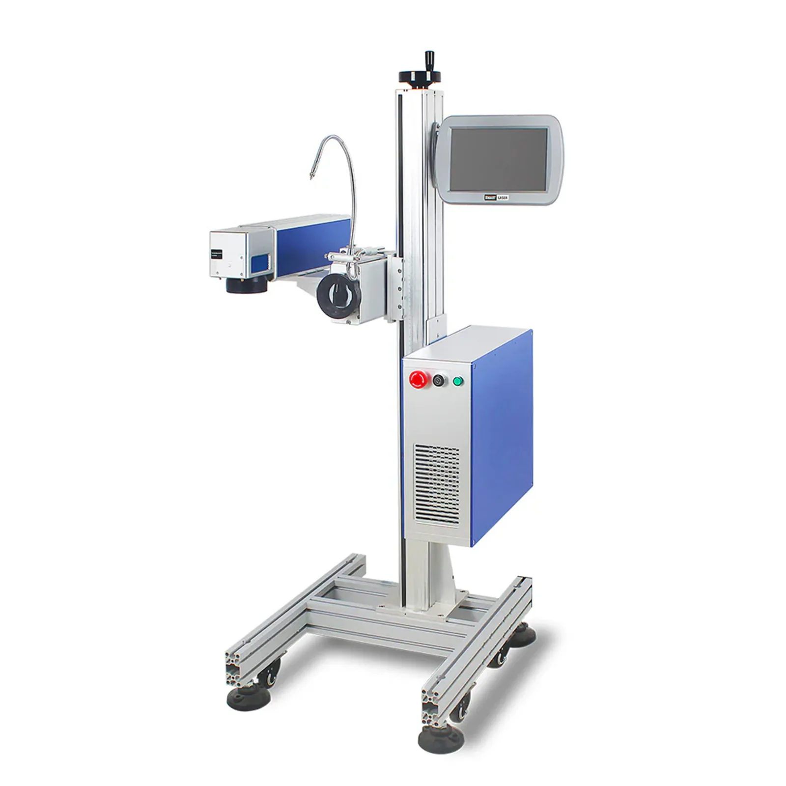
In flying or online marking, housings move continuously under the beam and the mark is written on the fly, synchronized with the conveyor motion. This can remove a stop-and-load step from the cycle, but it is only the better direction when the required takt time, mark window, part spacing and positioning method support continuous marking. The integration is a project-level evaluation, not an off-the-shelf choice.
Engineering takeaway: compare tray, inline and automatic options against the measured complete cycle — loading, positioning, marking, verification and unloading — rather than scan speed alone.
Durability, Validation and Acceptance
A mark on a charger housing must survive real use: daily plugging and unplugging, rubbing in bags and pockets, sweat and moisture, cleaning agents, and heat around the housing during operation. Whether a given mark survives depends on the housing material, the color and the laser parameters — so validation is sample-based, not assumed.
Abrasion, sweat, cleaning agents and temperature
Common durability checks for charger and adapter marks include rub and abrasion testing of the marked face, sweat and humidity exposure, cleaning-agent or alcohol wiping, and temperature cycling around the housing’s operating range. Housing integrity is part of the review as well: the mark should not thin or weaken a flame-retardant wall beyond the product design limits, which is one more reason thin-walled housings are marked with low-heat parameter windows on the real part rather than on flat coupons.
Sample testing: what to prepare and what gets verified
Sample testing is the practical way to confirm contrast, code readability, mark position and durability on the actual housing. Zhuorui Laser provides sample marking, parameter setup and process review as part of the factory’s standard service — a real housing and a clear mark specification produce a much more useful answer than a verbal description. For the sample test, send the housing or material sample, a drawing or photo, the required mark content and size, the target effect, the intended loading or part-presentation method, the production rate and expected volume, and any variable-data or scanner-verification requirement.
Acceptance dimensions
| Dimension | What is checked |
|---|---|
| Contrast and legibility | Rating text readable under the specified lighting, on the actual housing color |
| Character and code size | Meets the drawing or code-specification minimums |
| Code readability | Read-back with the intended scanner or verifier |
| Position accuracy | Mark position repeatable within the reader’s tolerance |
| Abrasion / rub | Rub test per the brand or customer requirement |
| Solvent / sweat / temperature | Exposure test defined by the application |
| Housing integrity | No weakening of thin walls or flame-retardant section beyond design limits |
| Data / verification flow | Correct variable data reaches the mark; intended reader or verifier response and NOK handling are confirmed where required |
| Cycle time | Measured on the real arrangement, including loading, positioning, marking, verification and unloading |
The acceptance criteria themselves are defined by the customer or the brand owner — Zhuorui Laser’s role is to set up and test against those criteria, not to invent them. Factory quality control and testing capability are described on the quality control and testing capability page.
How Do Sample-Test Results Determine the Final Machine Configuration?
The sample test should end with a configuration decision, not only a “marking works” conclusion. The accepted process window, part geometry, positioning tolerance, takt time and verification requirements together determine the laser source, optics, fixture and automation level that the production machine needs.
| Sample-test / production finding | Configuration decision it informs |
|---|---|
| Best acceptable mark requires UV, Q-switched fiber or another verified route | Laser source family and the process window to carry into production trials |
| Smallest text / code and total marking area are confirmed | Lens and marking-field direction, balancing usable field against feature quality |
| Curvature or height variation stays inside / exceeds focus tolerance | Standard 2D setup with controlled presentation, or 3D dynamic-focus evaluation |
| Required mark position is not repeatable with the current loading method | Dedicated fixture, multi-cavity tray, indexing presentation or CCD vision positioning |
| Measured complete cycle misses the required takt time | Tray density, indexing, automatic loading, inline / flying evaluation or a project-based automation review |
| Serial or code data changes by unit | Marking software plus the required database / MES or other data interface |
| Read-back is part of acceptance | Scanner or verifier integration with the required OK / NOK handling logic |
| Material or process creates a safety / fume-control requirement | Machine enclosure and interlock review and, where the material or process requires it, appropriate fume extraction or ventilation |
The final machine is therefore selected from the combined test result. A successful mark on one housing only answers the process-feasibility question; production release also needs the chosen configuration to repeat the accepted result at the required position and cycle time with the intended loading, data and verification flow.
Frequently Asked Questions
Can laser marking replace ink or pad printing on charger housings?
For many factories, yes — that is a common reason this application is evaluated. Laser marking avoids reliance on a surface-applied ink layer and removes ink, pads and related marking consumables from the process. Whether the laser result meets the required legibility, appearance and durability criteria still has to be confirmed on the actual housing by sample test.
Why does marking contrast differ between black and white charger housings?
Because the plastics respond to the laser differently: on many black housings the mark appears as a light or grey contrast, while on white or light housings it appears dark. Resin grade, flame-retardant additives and colorants all shift the result. The mechanisms are explained on the dedicated plastics material pages, and the specific outcome for your housing is a sample-test question.
Can certification marks and rating plates be laser marked?
Laser marking can be evaluated for the symbols and text that appear on a rating plate. What the plate must contain, and whether a laser-marked rather than molded or printed plate is acceptable under a given certification scheme or market regulation, is defined by the certification bodies and regulations — confirm that with your compliance function before committing the process.
Do curved charger housings need special fixturing or 3D marking?
Gentle curvature is first checked against the depth of focus: if the mark zone fits within the focus tolerance, standard marking works with a tray or cradle that presents the tangent plane. When the curve exceeds the tolerance, a 3D dynamic-focus approach or a smaller field with repositioning enters the evaluation.
Can the mark survive daily rubbing, sweat and cleaning agents?
It depends on the housing material, the color and the laser parameters — this is exactly what a sample test verifies. Rub testing, sweat and humidity exposure, alcohol or cleaning-agent wiping and temperature cycling are the common checks, and the acceptance criteria are defined by the customer or brand owner.
Can marking be integrated into a high-volume charger assembly line?
Yes. Tray-fed batch marking is a common starting point when parts can be located repeatably. Inline or flying marking and automatic loading are evaluated when the required takt time, part handling and line layout make continuous or automated presentation worthwhile. Integration feasibility — cycle time, positioning and data interface — is reviewed as a project, and the relevant solution pages describe the approaches.
Sample Test or Quote
The fastest way to confirm what is achievable on your charger or adapter housing is a sample test on the actual material, color and finished surface. Send the housing or material sample, a drawing or photo, the mark content and size, the target effect and acceptance criteria, the intended loading method, the production rate, and any variable-data or scanner-verification requirement. The test result can then be used to define the laser direction, optics, fixture or vision requirement, production method and verification configuration.
For any charger or adapter marking workstation, the equipment review includes laser safety controls for the specific machine configuration — enclosure and interlock options are particularly relevant when the station runs unattended in a high-volume production area.