
Hand Tools · Sockets & Tooling · Power-Tool Components
Tool Laser Marking
Plan laser marking for hand tools, sockets, measuring tools and power-tool components by defining the material and surface, required mark result, part geometry, handling method, production rate and sample-acceptance criteria before choosing the final machine configuration.
Tool / Workpiece Scope
Which Tools and Components Are Commonly Laser Marked?
Start with the actual workpiece, not the machine name. Tool families differ in material, finish, available marking area, curvature, assembly state and production handling, so each marked location should be defined before sample testing.
Manual tools, gauges and workshop tools
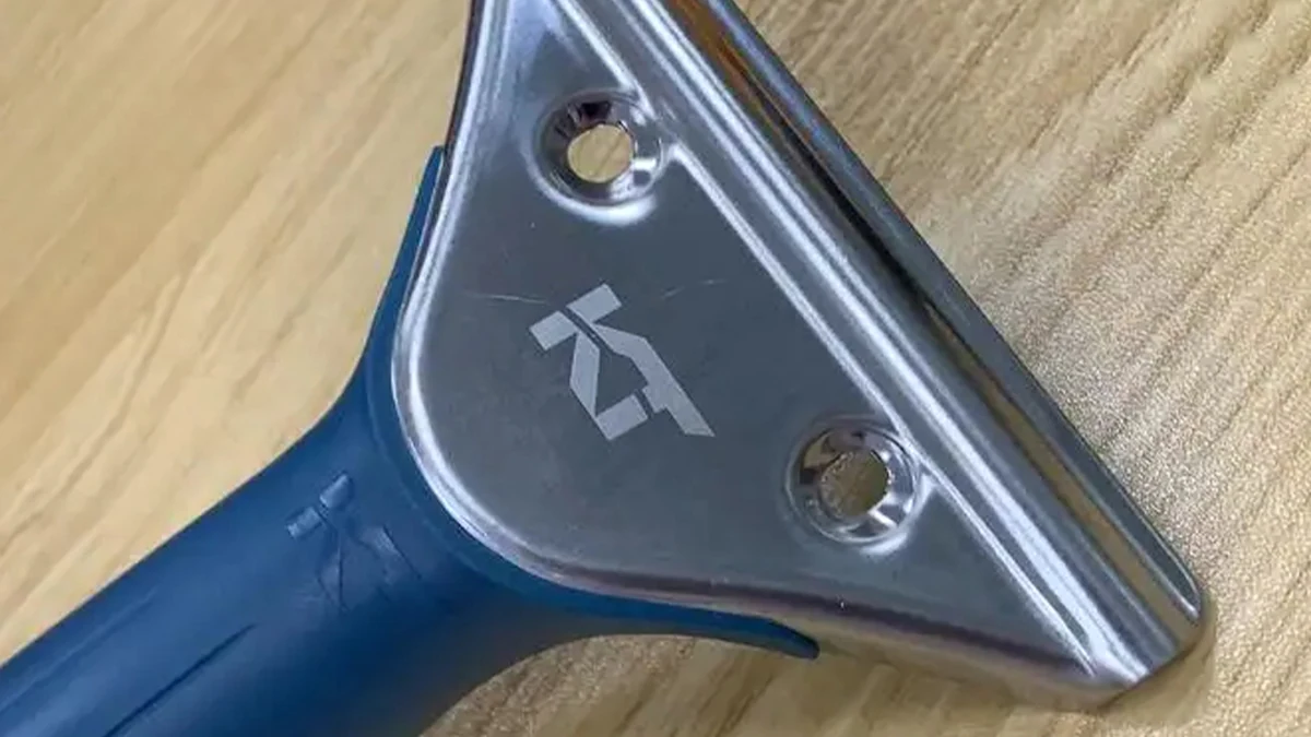
Wrenches, pliers, screwdrivers, cutters, hammers, clamps, rulers, gauges and similar tools may need visible identification that remains readable through handling and service.
- Flat, forged, narrow or recessed marking zones
- Size, model, brand, serial or inspection information
- Bare, polished, oxidized, plated or coated surfaces
Sockets, bits, shafts, holders and replaceable parts
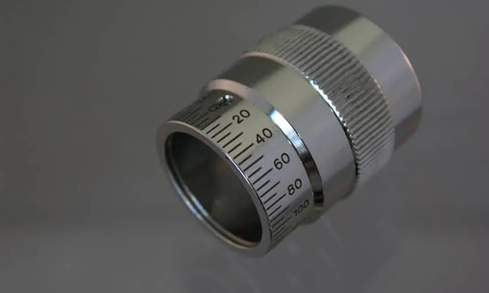
Small cylindrical or interchangeable components often make positioning and mark orientation as important as the laser process itself.
- Curved or circumferential marking areas
- Small characters, size IDs or machine-readable codes
- Multiple diameters and frequent product changeover
Power-tool components and housings
Drills, grinders, saws, drivers and related products can combine bare metal, coated metal, molded plastic and labels in one assembly. Each intended marking location should be evaluated separately.
- Model, specification, compliance and service information
- Serial, batch or traceability codes
- Access around guards, handles, inserts and assembled features
Why Mark
Why Are Tools Marked?
The reason for marking determines what information is needed, how long it must remain readable and how the result should be accepted. A brand logo, a socket-size mark and a serialized Data Matrix code can all be on “tools,” but they create very different process and verification requirements.
Product and size recognition
Brand, model, size, direction or specification marks help operators and users identify the correct tool quickly.
Serial, batch and production history
Variable data can connect a physical tool or component with manufacturing, quality, service or inventory records when the data workflow is defined.
Quality, calibration and maintenance status
Gauges, measuring tools and controlled workshop equipment may need inspection, calibration, asset or maintenance identification that remains readable for the required service period.
Marking Content
What Is Commonly Marked on Tools?
| Mark content | Purpose | Information before testing | Acceptance check |
|---|---|---|---|
| Brand, logo and model | Product identity | Artwork, mark size, location and visual target | Appearance, placement and consistency |
| Size, scale or specification | Correct tool selection and use | Character height, direction and tolerance | Legibility at the expected viewing distance |
| Serial number or batch code | Production and service traceability | Data format, numbering source and duplicate control | Correct data, position and record association |
| QR or Data Matrix code | Digital traceability or inventory | Code size, scanner, verification target and geometry | Readability before and after the required durability test |
| Inspection or calibration ID | Quality and maintenance status | Workflow, update rules and required durability | Correct status, revision and readability |
Result Variables
What Determines the Laser Marking Result on Tools?
The tool name alone does not select the laser. The result comes from the interaction between the actual substrate and surface, the intended mark effect, the available marking zone and the production conditions.
| Variable | Why it changes the result | What to define before testing |
|---|---|---|
| Base material | Tool steel, stainless steel, aluminum and molded plastics absorb laser energy differently and support different marking mechanisms. | Known alloy, grade or resin family; supplier information if available |
| Surface condition | Polishing, black oxide, plating, paint, powder coating, anodizing and other finishes can become the actual layer interacting with the laser. | Finish type, color, coating or plating condition, and whether that layer must be preserved |
| Required mark effect | A dark contrast mark, light contrast mark, engraving or controlled coating removal uses a different process window. | Visual target, acceptable depth or material removal, and forbidden surface changes |
| Mark content and size | Large logos are more tolerant than small characters or dense Data Matrix codes that depend on resolution and edge quality. | Artwork, smallest feature, code module size, field size and scanner requirement |
| Geometry and access | Curvature, recesses, height changes and nearby features affect focus, beam access and repeatable placement. | Diameter, height variation, mark angle, available clearance and assembly stage |
| Wear environment | Oil, coolant, rubbing, cleaning, corrosion exposure, heat or impact can change what “durable” must mean for the project. | Actual service exposure and a defined pass/fail durability test |
| Production rate and handling | A process that works on one hand-loaded sample may not meet the required takt time, changeover or repeatability in production. | Parts per batch or hour, takt target, operator steps, SKU count and changeover expectation |
| Data and verification | Serialization and machine-readable codes add data-control and verification requirements beyond simply creating a visible mark. | Data source, duplicate-control rule, scanner, record association and reject logic |
Target Result
What Result Should You Target?
Define the pass condition before optimizing laser parameters. The best-looking sample is not automatically the best production result if it damages the surface, fails the scanner, wears away in service or takes too long to produce.
Readable contrast
Text, size marks and logos should be readable under the intended viewing conditions without requiring excessive surface damage.
The correct mark mechanism
Agree whether the target is surface contrast, color change, engraving or controlled removal of a coating before judging the sample.
No unacceptable functional damage
Check for burrs, sharp edges, unwanted coating removal, excessive roughness or changes that could affect fit, corrosion protection or use.
Human and scanner readability
Machine-readable codes should be tested with the intended scanner or verification method, not judged only by appearance.
Stable position and appearance
The mark should remain within the required position and quality range across representative parts, orientations and product variants.
Wear resistance after real exposure
Wear resistance is an acceptance requirement, not an automatic claim. Test the mark against the handling, oil, coolant, cleaning, abrasion or environmental exposure that matters to the tool.
Define “permanent” as a test
Specify the exposure method, duration or cycle count, pass/fail rule and whether the final requirement is visual recognition, scanner readability or both. Compare the result before and after the defined exposure instead of relying on a general “permanent mark” description.
Geometry & Handling
How Do Geometry, Positioning and Part Handling Affect the Process?
Geometry determines more than whether the laser can reach the surface. Production also depends on how the operator or automation establishes the same position, focus and orientation from part to part.
Flat, narrow and recessed areas
Confirm clear line of sight, focal access and whether ribs, guards, handles or fixtures block the marking zone.
Sockets, shafts and cylindrical parts
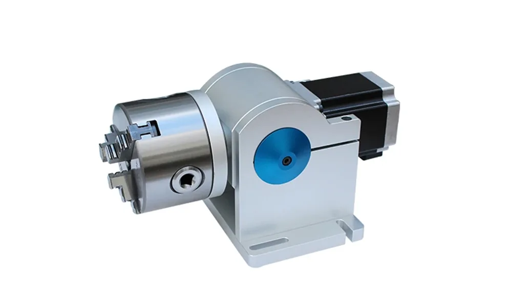
Record diameter, mark width, angle and whether the mark is local or circumferential. Curvature can create focus and distortion limits that must be checked on the real part.
Prevent reversed or shifted loading
Define the locating surfaces and orientation features. A simple fixture may be enough for one part family; mixed variants may require more controlled positioning.
Multiple sizes and frequent changeover
Wrench sizes, socket diameters or housing variants can require adjustable fixtures, multiple nests, stored recipes or another changeover strategy.
Mark before or after assembly
Evaluate whether handles, guards, inserts or adjacent materials restrict access after assembly and whether the mark must align with finished-product features.
Single-part or batch loading
Compare manual one-part loading with multi-part fixtures or automated handling against takt time, operator motion, verification and changeover requirements.
First-Test Laser Route
Which Laser Route Should Be Tested First?
Choose the first test from the material and top surface, then compare the result against the required effect. The routes below are starting directions for sample evaluation, not universal machine prescriptions.
| Tool surface / workpiece | Typical first-test direction | What the sample must resolve |
|---|---|---|
| Bare tool steel, carbon steel, stainless steel and many metal components | Start with a 1064 nm fiber-laser route. Compare a MOPA fiber source when wider pulse-width control is useful for the required contrast, surface effect or heat input. | Contrast versus engraving, surface roughness, edge quality, cycle time and durability |
| Black oxide, plated, painted or powder-coated metal | First define whether the top layer must be preserved, modified or removed. Fiber or MOPA fiber is often a practical metal/coating comparison route, but the actual finish must be sampled. | Coating damage, exposure of the substrate, color consistency, corrosion-protection implications and wear resistance |
| Anodized or otherwise surface-treated aluminum tool parts | Compare routes according to the anodized layer, color and desired effect rather than treating all aluminum alike. Fiber is a common starting route; UV or another wavelength may be compared when finer or lower-thermal-impact results are required. | Contrast, layer integrity, detail resolution and whether the intended mark is produced in or through the surface treatment |
| Plastic power-tool housings and molded components | Test the actual resin, pigment and additives. Fiber can work on some engineered plastics; UV or 532 nm green can be useful comparison routes for sensitive, light-colored or difficult formulations. | Color change, foaming or ablation behavior, melting, heat halo, contrast, fine-detail quality and consistency between material batches |
| Mixed-material assemblies or unknown supplier finishes | Separate each marked location and identify the top layer before selecting a route. Do not assume one parameter set or one laser direction will suit every surface on the assembly. | Material-specific response, access, adjacent-part risk and whether separate recipes or marking stations are required |
MOPA is a fiber-laser subtype, not a separate wavelength family
The practical reason to compare a MOPA fiber source is its pulse-control range, not because “MOPA” describes a different material category. Final selection should still be based on the actual sample result and production window.
Failure Diagnosis
Where Do Tool Laser Marking Projects Commonly Fail?
A failed sample is useful when the symptom is connected to a testable cause. Change one relevant variable at a time and confirm the correction on representative parts instead of treating power as the only adjustment.
| Observed problem | Check first | How to verify the correction |
|---|---|---|
| Contrast is too low or inconsistent | Material/finish variation, intended marking mechanism, focus and process window | Retest on identified surface batches and compare contrast under the same viewing condition |
| Mark changes across a curved socket or shaft | Focus variation, curvature, mark width, orientation and whether controlled rotation is needed | Check the full marking area on the real diameter and repeat after reloading the part |
| Plating, oxide or coating is damaged unintentionally | Whether the process should preserve or remove the top layer, plus energy concentration and coating variation | Inspect the layer around and inside the mark and repeat the required corrosion/wear test where applicable |
| Engraving leaves rough edges or unacceptable burr | Depth target, passes, pulse/energy distribution and whether engraving is actually required | Measure or inspect the final surface against the functional acceptance rule |
| Small QR/Data Matrix code does not scan reliably | Code size, module size, contrast, edge definition, focus, curvature and scanner setup | Use the intended scanner or verification method across multiple marked parts and positions |
| Mark position shifts between parts | Fixture datum, part tolerance, operator loading direction and recipe selection | Reload and mark repeated samples, then compare position against the defined tolerance |
| Visual sample passes but durability fails | Marking mechanism, depth/effect, coating behavior and whether the test reflects real service exposure | Repeat the defined wear/cleaning/oil test after process adjustment |
| Different tool batches react differently | Alloy or resin change, heat treatment, plating/coating supplier, color, additives or surface-preparation variation | Record batch identity and confirm the process window on representative or worst-case samples |
Production Workflow
How Does a Tool Marking Process Move Into Production?
Production planning begins after the mark itself is feasible. The workflow must control the correct workpiece, orientation, data, mark position, acceptance decision and changeover without adding avoidable operator steps.
1. Identify the part
Confirm tool family, SKU, surface condition, assembly stage and the correct marking recipe.
2. Load the workpiece
Use the defined locating surfaces or nest and prevent reversed or incorrect orientation where required.
3. Confirm mark data
Load fixed artwork or receive the required serial, batch, code or inspection data with duplicate-control rules where applicable.
4. Mark the part
Run the validated process within the approved focus, field, recipe and cycle-time window.
5. Verify the result
Perform the defined visual, position or scanner check rather than relying only on the machine completing a cycle.
6. Handle nonconformance
Define what happens to an unreadable, misplaced or cosmetically unacceptable mark and prevent duplicate variable data.
7. Record required data
Where traceability is needed, associate the marked identifier with the required production, quality or service record.
8. Change over safely
Control fixture, focus, recipe and data changes between tool sizes or product families and verify the first part after changeover.
Sample Acceptance
How Should Tool Marking Samples Be Accepted?
Do not approve a machine direction from one attractive sample. The sample plan should represent the actual material and finish range, difficult geometries and the production result that must be repeated.
| Acceptance area | What to check | Recommended sample evidence |
|---|---|---|
| Visual result | Contrast, edge quality, appearance and consistency against the agreed target | Representative parts viewed under the intended inspection condition |
| Content accuracy | Correct logo, text, size, serial, batch or inspection information | Approved artwork/data file and marked-part comparison |
| Code readability | QR/Data Matrix or other code can be read by the intended scanner or verification method | Multiple scans across representative parts, locations and code values |
| Surface integrity | No unacceptable burr, sharp edge, melting, coating damage or functional change | Visual/magnified inspection and any project-specific dimensional or surface check |
| Durability | Mark remains acceptable after the defined rubbing, oil, coolant, cleaning, corrosion or other service exposure | Before/after comparison using the project-defined test method and pass/fail rule |
| Production repeatability | Position, quality and cycle time remain acceptable across reloads, variants and representative surface batches | Repeated parts including difficult geometry, expected SKU range and worst-case samples where practical |
Final Machine Configuration
How Do Sample-Test Results Determine the Final Machine Configuration?
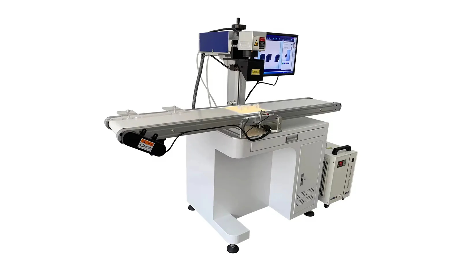
Sample testing is not only a feasibility check. It converts the workpiece, mark-quality and production requirements into the optical, mechanical, software, safety and automation choices needed for the actual application.
| What the test or production review shows | Configuration decision it can affect |
|---|---|
| The material and finish respond best within a specific process window | Laser source family or subtype, power range and pulse-control capability |
| The required mark is small, dense or covers a defined field | Optical setup, field lens, marking field, working distance and resolution requirement |
| The surface is cylindrical or the mark wraps around the part | Rotary/indexed positioning strategy, fixture design and motion sequence |
| Part height or surface angle varies beyond a simple fixed-focus setup | Z adjustment, focus-control method or a 3D/dynamic-focusing approach where justified by the geometry |
| Part position varies or several similar variants share a station | Fixture strategy, poka-yoke features and whether vision-assisted positioning is useful |
| Serial numbers or machine-readable codes are required | Marking software, variable-data input, scanner/verification hardware and data-record logic |
| The takt target cannot be met with one-at-a-time manual handling | Multi-part fixtures, operator workflow changes or a higher level of automation after the marking process itself is validated |
| Marking removes coating or generates process residue | Fume/dust extraction and enclosure details appropriate to the actual material and process |
| The operator, plant layout or integration requires controlled access | Enclosure, guarding, interlocks and integration layout based on the final system risk assessment |
Next Step
Evaluate Your Tool Marking Requirement
Share the actual tool, marked surface, target result, artwork or variable code, mark location, geometry, production rate and acceptance requirement. Zhuorui Laser can review the application and define a sample-test path before the final equipment configuration is selected.
Prepare: tool photos or drawings; material and surface information; mark file; mark size and location; code and scanner requirement; batch size and takt time; loading method; durability test; destination and voltage.