
Laser Marking Machine Applications · Powertrain
Engine and Transmission Parts Laser Marking for Serial Numbers, Data Matrix Codes and Traceability
Engine builders, transmission manufacturers and powertrain suppliers use laser marking for serial numbers, part numbers, Data Matrix and QR codes, batch and date codes, matched-set identification, balance marks and assembly information on blocks, heads, crankshafts, connecting rods, gears, shafts, valve bodies and housings. This page helps you turn a powertrain marking task into an engineering test plan: define the actual material and surface, the required mark result, the marking location and handling method, the laser route to test first, the likely failure modes, the production workflow and acceptance criteria, and then use the sample results to determine the final machine configuration.
Request a Quote Browse Typical Powertrain Marking Tasks
- Typical engine, transmission and driveline parts and what is marked on them
- Material, heat-treatment, surface and process variables that change the result
- Target mark result, geometry, fixturing, handling and laser route
- Failure modes, production workflow and sample acceptance criteria
- Test result → source, field, fixture, rotary, 3D, vision, data or automation configuration
Application Overview
What Is Laser Marking Used for on Engine and Transmission Parts?
Laser marking is used for permanent part identification, traceability and assembly information on engine, transmission and driveline components. The useful engineering question is not only whether a part can be marked, but whether the required serial number, Data Matrix code or process mark can be produced on the specified surface, in the allowed location, at the required production rate, and remain acceptable through the downstream handling or service exposure defined for that part.
This page focuses on part-level powertrain marking and the decisions needed before equipment selection. Typical parts and marking content are mapped below; vehicle-level VIN identification is covered separately on VIN and Chassis Marking, while the broader component view is on Auto Parts Laser Marking.
Industry Drivers
Why Engine and Transmission Parts Are Laser-Marked
The reasons powertrain suppliers adopt laser marking are practical and commercial. Understanding the driver helps you decide what content, quality level and validation your marking task actually needs.
When marks must feed a production database or a PLC / MES environment, the marking station becomes part of a data chain. For serial-number control, work-order data transfer, code reading and database integration, see the Traceability, PLC, MES & Data Integration Solution. Vehicle-level identification such as VIN is a separate regulatory area covered on the VIN and Chassis Marking page; this page covers part-level powertrain marking.
Typical Parts
Typical Engine and Transmission Parts and Their Marking Tasks
The table below links common powertrain part families to typical marking content, geometry and configurations worth evaluating. Use it as an initial engineering screen rather than a machine specification; final results still depend on the exact part, material and surface state.
| Part family | Typical marking content | Typical geometry / surface | Configuration direction |
|---|---|---|---|
| Engine blocks and cylinder heads | Engine serial, part number, date, DMC | Machined pad on as-cast block; multi-face, deep pockets | Standard machine with fixture; evaluate 3D or multi-position for deep/recessed areas |
| Crankshafts and camshafts | Serial, part number, balance and timing marks | Cylindrical journals, webs; machined or ground faces | Rotary / circumferential marking; fixture for orientation |
| Connecting rods and pistons | Part number, batch, matched-set code, weight grade | Small machined faces, cylindrical skirt | Standard machine; matched-set tracking often needs data integration |
| Engine valves and tappets | Part number, grade, heat-treat code | Small flat face, hardened stem end | Standard machine; high-volume feeding for valve lines |
| Flywheels and flexplates | Serial, part number, balance marks | Flat machined face, bolt circle | Standard machine; rotary indexing at higher volume |
| Gear sets and synchronizers | Part number, serial, heat-treat info, paired-set code | Flat face or hub on carburized gear; teeth area avoided | Standard machine; orientation fixture; vision if gear orientation varies |
| Shafts, half-shafts and CV joints | Part number, serial, batch, torque or direction marks | Cylindrical shafts, machined flats | Rotary / circumferential marking; online at assembly lines |
| Valve bodies, pump bodies and manifolds | Part number, DMC, date, flow code | Machined faces, ports and pockets on cast body | Standard or multi-position; 3D evaluation for pocketed faces |
| Transmission, clutch and torque-converter housings | Serial, DMC, date, ratings | As-cast and machined faces, 3D contour | Evaluate 3D curved-surface or multi-position marking |
| Differential housings and carriers | Serial, part number, DMC, ratio code | Cast body, machined pads, curved faces | Multi-position fixture or 3D evaluation |
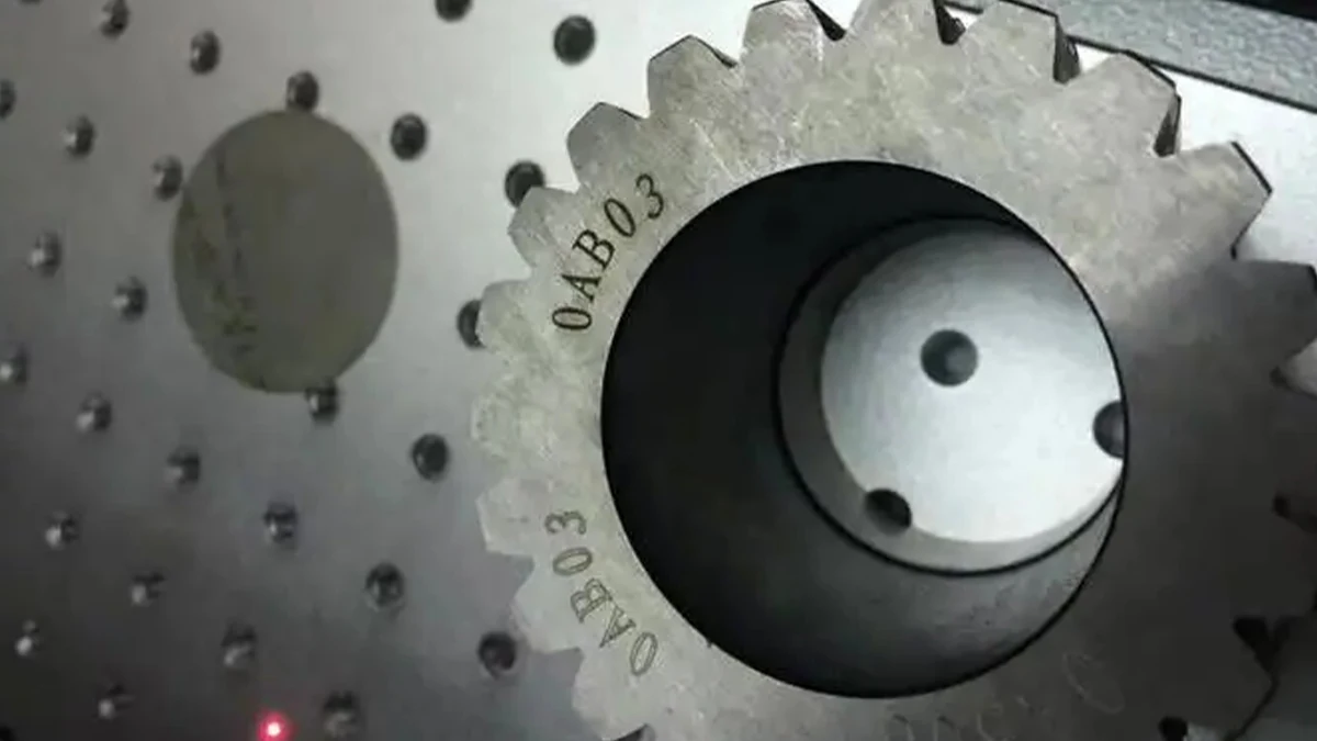
This page focuses on mechanical engine, transmission and driveline parts. Battery, e-drive and electrical connector marking are covered separately.
Result Variables
What Determines Laser Marking Results on Engine and Transmission Parts?
The part name alone does not determine the process. A crankshaft, gear, housing or cylinder head can behave very differently depending on material condition, surface finish, marking location, geometry and the state in which the part reaches the marking station. These inputs should be defined before choosing a machine configuration.
| Decision input | Powertrain examples | Why it changes the result |
|---|---|---|
| Material and metallurgical condition | Cast iron, carbon/alloy steel, aluminum; carburized, nitrided or other heat-treated surfaces | Material composition and surface treatment change laser interaction, contrast, material removal and the usable process window. |
| Surface condition | As-cast, machined, ground, coated, plated, oxidized, oily, coolant-wet or protected with anti-rust film | Roughness, coatings and residue can change contrast and consistency even on the same base material. |
| Marking location | Machined pad, hub/end face, shaft OD, web, pocket, curved housing face | The location determines access, focus, available mark area and whether the mark is near a sealing, mating, bearing, balanced or otherwise protected functional surface. |
| Mark content and feature size | Serial characters, Data Matrix modules, logos, balance or assembly marks | Small features and machine-readable codes place tighter demands on focus, field size, contrast and positioning repeatability. |
| Part geometry and presentation | Flat, cylindrical, height-varying, recessed, multi-face; fixed orientation or random presentation | Geometry determines whether a fixed fixture is enough or whether rotary motion, 3D focus compensation, vision or multi-position handling should be evaluated. |
| Production condition | Manual load, pallet, tray, conveyor, robot, washing state, takt time, verification and reject handling | The station must meet the full production cycle, not only the laser-on time, and the tested surface condition should match the real process stage. |
Material guides are supporting inputs, not a separate project path. If the main uncertainty is the response of steel, cast iron, aluminum, a hardened layer or a coating, use Materials · Metals or Coatings & Surface Treatments to understand the substrate, then return to the actual powertrain part, geometry, production condition and acceptance target for sample testing.
Target Result
What Marking Result Should You Target?
A visible mark is not automatically an acceptable powertrain mark. Define the result in terms that can be checked on the real part: what must be readable, how the code will be inspected, whether depth is actually required, what exposure the mark must survive, and which functional surfaces must remain unaffected.
| Target | What to define before testing | Acceptance direction |
|---|---|---|
| Human-readable identification | Character content, size, location and visual contrast expected on the specified surface | Legible under the agreed inspection conditions and stable over the required production run. |
| Machine-readable Data Matrix / QR | Code type, data content, module size, mark area, reader/verifier requirement and viewing conditions | Pass the reader or verification method required by the customer or production system. |
| Specified mark depth | Whether depth is functionally required, the permitted range and where it may be measured | Meet the drawing or process requirement without unnecessary material removal or damage to protected surfaces. |
| Durability | Relevant cleaning, oil/coolant exposure, temperature, handling, abrasion or other defined downstream/service conditions | Remain acceptable after the specific exposure sequence required for the part. |
| Placement and consistency | Datum, allowable position tolerance, appearance variation and protected zones | Repeat within the agreed location and quality window without marking sealing, mating, bearing, balanced, loaded or other restricted areas. |
For serial numbers and codes, the required data format comes from your drawing, customer or traceability system. For durability or depth requirements, use the actual acceptance specification rather than assuming that a darker or deeper mark is automatically better.
Geometry, Fixturing & Handling
How Do Part Shape, Positioning and Loading Affect the Marking Setup?
The laser source is only one part of the station. Powertrain parts must also be presented at the correct height and orientation, held repeatably, and loaded at a rate that matches production. Geometry and handling therefore determine whether the project needs a simple fixture, rotary motion, 3D focus control, vision, indexing or automation.
| Part / handling condition | Typical example | Configuration direction |
|---|---|---|
| Flat surface with repeatable datum | Block pad, flywheel face, housing pad | Standard marking setup with a dedicated fixture and fixed focal position. |
| Cylindrical or circumferential mark | Crankshaft, camshaft, half-shaft, shaft OD | Evaluate rotary / circumferential marking and a fixture that controls axial and angular position. |
| Height variation, curved face or recess | Transmission housing, valve body, pocketed casting | First confirm whether orientation or fixturing can keep the mark within focus; if not, evaluate 3D marking or a multi-position method. |
| Variable orientation | Gear or casting presented with inconsistent angular position | Improve mechanical location first; where natural variation remains, evaluate vision positioning. |
| Multiple faces or stations | Block, valve body or differential carrier with more than one mark location | Use indexed fixtures, multiple positions or an automatic marking cell when the production sequence justifies it. |
| High-volume part flow | Gear, valve or shaft production line | Compare manual fixture loading, tray/pallet indexing, conveyor, feeder or robot presentation against the required full cycle time. |
When evaluating throughput, count load, datum/orientation, clamping, marking, code reading, reject handling and unload. A short laser marking time does not by itself prove that the station will meet the production takt.
Technology Direction
Which Laser Route Should Be Tested First?
For metal powertrain parts, fiber is usually the first route to evaluate; MOPA fiber is worth comparing when the required result needs a wider parameter-tuning range. UV or CO₂ are mainly relevant when the task includes heat-sensitive, plastic or other non-metal components. Final selection should come from the actual surface, feature size, result target and sample test — not from the part name alone.
| Laser family | Typical reason to test it | What the sample test must prove |
|---|---|---|
| Fiber (Q-switched, ~1064 nm) | Common starting route for serials, 2D codes and identification on many bare metal powertrain surfaces | Required contrast or depth, feature quality, readability, durability and cycle time on the actual surface. |
| MOPA fiber | Compare when pulse-width/frequency flexibility may provide a wider process window for contrast, fine features or thermal control | Whether the additional tuning range materially improves the required result or production margin versus the baseline fiber test. |
| UV (~355 nm) | Fine marking on selected heat-sensitive components or non-metal parts where a different absorption/thermal response is useful | Required feature quality and acceptable surface change on the exact material formulation. |
| CO₂ (wavelength per machine configuration) | Selected plastics and other non-metal powertrain components | Whether the actual material absorbs the chosen wavelength and produces the required contrast or surface effect. |
Power is selected within a validated process window and production requirement; higher power does not automatically mean a better mark. Field size, spot size, feature size, focal tolerance and cycle target must be evaluated together. For machine families, see fiber laser marking machines and Products.
Failure Modes
What Are the Common Failure Modes on Powertrain Parts?
The most useful sample test is not only a search for a good-looking mark. It should also reveal where the process becomes unstable, unreadable, mispositioned or too slow for production.
| Failure symptom | Likely drivers to investigate | Engineering response |
|---|---|---|
| Contrast varies across a casting or batch | Roughness, porosity, oxide, residue, surface finish or process-window sensitivity | Test representative surface variation, improve cleaning/location, and compare parameter windows rather than approving one ideal sample. |
| Data Matrix / QR reads inconsistently | Module size, contrast, focus, glare, roughness, positioning or reader conditions | Test the actual code size and reading setup; adjust field/optics, surface location, focus or marking parameters as required. |
| Mark is too shallow, too aggressive or visually unstable | Energy density, pulse conditions, number of passes, surface state or an unrealistic target | Return to the defined acceptance target; do not increase power or depth without checking the functional requirement. |
| Part of the mark loses focus | Height variation, pocket depth, curved surface, fixture stack-up or working-distance limitation | Improve fixture/orientation first; evaluate 3D or another multi-position strategy when the geometry cannot be held inside the usable focus range. |
| Circumferential mark is stretched, shifted or does not close correctly | Part diameter, rotary setup, clamping, angular reference or motion coordination | Validate the real diameter range and fixture repeatability; tune the rotary process on representative parts. |
| Mark location drifts onto a protected surface | Poor datum, part variation, wrong fixture, orientation error or uncontrolled presentation | Define protected zones and position tolerance; improve mechanical location or add position verification where necessary. |
| Mark degrades after downstream processing | Cleaning, coating/plating, abrasion, oil/coolant exposure, heat or later machining | Test the mark in the same process sequence in which it will be used, or move the marking operation to the correct process stage. |
| Station misses takt or traceability logic fails | Load/locate/read/reject time, data handshake, serial control or automation bottleneck | Measure the full station cycle and data sequence; change handling, verification or integration architecture rather than blaming laser speed alone. |
Production Workflow
How Does Laser Marking Fit Into the Production Workflow?
Before machine selection, define where marking sits in the manufacturing sequence and how each part moves through the station. The tested surface state should match the state that will actually be marked in production.
- Choose the process stage. Confirm whether marking happens after machining, heat treatment, washing, coating/plating or final assembly steps. A different process stage can mean a different surface and a different durability requirement.
- Load and locate the part. Define manual fixture, tray, pallet, conveyor, feeder or robot presentation; identify the datum and orientation that place the mark in the correct area.
- Provide the marking data. Determine whether the content is fixed, operator-entered, scanned from a work order, or supplied by PLC / MES / database logic.
- Mark under controlled conditions. Hold the required focus, orientation and surface condition while the validated parameter set is applied.
- Verify the result. Check mark presence, human readability and, where required, machine-readable code performance using the agreed reader/verifier and inspection conditions.
- Accept, reject and record. Define what happens to a failed mark or data mismatch and whether the station must signal, segregate, rework or record the part.
- Unload and hand off to the next process. Confirm that the complete load-to-unload cycle meets takt and that later processes do not invalidate the approved mark.
Where unique serials, recipe control, read-back or database records are required, review the Traceability, PLC, MES & Data Integration Solution. Automation scope should be based on the real line sequence, I/O and reject logic rather than assumed from the marking task alone.
Sample Acceptance
How Should a Powertrain Sample Be Tested and Accepted?
A sample test should reproduce the important production conditions and finish with explicit acceptance decisions. Approving only the best-looking sample is not enough; the test should show whether the mark remains inside the required window across representative surfaces, positions and handling conditions.
- Representative part state — correct material grade, heat-treatment condition, cast/machined/coated surface and realistic oil, coolant or cleaning state.
- Required content at real size — smallest characters, real Data Matrix/QR module size, line width and actual mark area.
- Target result — agreed contrast, depth where specified, readability and appearance rather than an undefined “good mark.”
- Location and repeatability — mark position against the real datum, pocket, cylindrical surface or protected-zone boundary.
- Code acceptance — reader or verifier test when machine-readable identification is required, using the agreed inspection conditions.
- Durability exposure — the cleaning, oil/coolant, temperature, abrasion, handling or downstream process that the actual requirement calls for.
- Process-window margin — more than one ideal parameter point; check whether normal surface variation still produces an acceptable result.
- Full station cycle — load, locate, clamp, mark, read, reject logic and unload against the required takt.
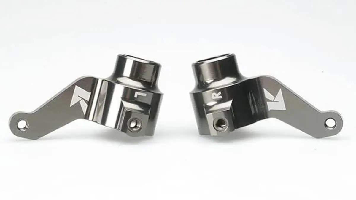
Zhuorui Laser assembles, configures and tests complete laser marking machines, and sample marking can be used to evaluate an application before the final equipment configuration is fixed. Send representative parts, drawings or photos, marking content, surface condition, target result and production requirements through Contact Us.
Test Result → Machine Configuration
How Do Sample-Test Results Determine the Final Machine Configuration?
The machine should be configured from what the test reveals, not from the part name or a fixed “standard vs. custom” ladder. Each failed or marginal test condition should point to the specific source, optics, motion, fixture, verification or automation function that needs to change.
| Sample / production finding | What it means | Configuration consequence to evaluate |
|---|---|---|
| Q-switched fiber meets contrast/readability/durability with a stable process window | The basic laser-material route is proven | Keep fiber and finalize practical power margin, lens/field, fixture and cycle requirement rather than changing technology without a reason. |
| Baseline fiber result is acceptable only in a narrow window or needs more pulse-control flexibility | Source parameter flexibility may be the limiting factor | Compare MOPA fiber on the same part and acceptance criteria; adopt it only if the test shows a real process-window benefit. |
| Small code or fine feature passes only with a smaller field / better spot condition | Optical field and feature-size trade-off is limiting quality | Select lens and marking field around the validated feature requirement; do not choose the largest field by default. |
| Flat fixture test passes, but curved/recessed locations lose focus | Geometry, not source power, is the limiting condition | Improve part orientation/fixture; if height variation remains outside the usable focus range, evaluate 3D or a controlled multi-position setup. |
| Cylindrical mark cannot be completed inside a stable tangent area | Part rotation is required for the real mark geometry | Add rotary motion and a diameter/axial locating fixture validated on the actual shaft, crankshaft or cylindrical part range. |
| Mark location varies because the incoming part orientation varies | Part presentation is limiting repeatability | First improve mechanical datum/fixture; if legitimate variation remains, evaluate vision positioning. |
| Mark passes, but fumes, debris or operator exposure require additional control | The marking process is viable but the workstation configuration is incomplete | Add appropriate enclosure, extraction and safety controls as part of the complete machine review; final laser-safety classification depends on the complete system. |
| Manual load → locate → mark → read → unload misses takt | Handling or station architecture is the bottleneck | Evaluate indexing, tray/pallet flow, conveyor, feeder, robot loading or a multi-station cell based on measured time losses. |
| Unique serials require recipe control, read-back and database association | The station is part of the traceability system | Include scanner/reader, PLC/MES/database handshake, duplicate prevention and reject logic in the project configuration. |
Final source power, field size, fixture, motion axis, 3D, vision, extraction, verification and automation scope should therefore be tied back to a passed sample result and the measured production requirement. For standard equipment use Request a Quote; for project-based automation or custom integration use OEM & Custom Inquiry.
FAQ
Common Questions About Engine and Transmission Parts Laser Marking
What is laser marking used for on engine and transmission parts?
Permanent identification and traceability: engine serial numbers, part numbers, QR and Data Matrix codes, batch and date codes, matched-set and balance marks, and assembly or heat-treat information. The common thread is permanent, non-contact identification with durability requirements defined by the part’s handling and service environment.
Can my part — a cast block, a carburized gear or a shaft — be laser-marked?
Most metal powertrain parts can be laser-marked, but the achievable contrast, depth and durability depend on the exact material grade, surface state (cast, machined, hardened, coated or oily), target effect and geometry. The typical-parts table above shows the configuration direction usually evaluated; the final answer is confirmed on a real sample of your part.
Why do casting surfaces and hardened gear faces mark differently?
As-cast surfaces are rough and can contain porosity, so contrast varies from point to point; hardened layers such as carburized or nitrided gear faces change how the laser interacts with the material, narrowing the contrast and depth window. This is why marking is often placed on a machined pad or a non-loaded face, and why parameters must be confirmed on real parts. If the main uncertainty is substrate behavior, evaluate the exact material grade, hardened layer, coating or surface condition before fixing the process window.
When should a powertrain part be laser-marked in the production process?
Marking should be placed at the process stage where the surface condition and traceability requirement are both stable enough to validate. Confirm whether the real station is before or after machining, heat treatment, washing, coating/plating or final assembly, then test the part in that representative state. A mark approved before a later surface-changing process may not represent the final production result.
How durable is a laser mark on a powertrain part, and how is that verified?
Durability is part-specific: it depends on the material, surface, mark characteristics and the environment the part sees — for powertrain parts this may include oil immersion, temperature cycling, vibration and wear. Durability should be verified on representative samples under the exposure conditions and acceptance criteria required by your customer or standard. No machine vendor can guarantee mark life without testing your part.
Can a high-volume gear or engine line use online marking, and how do I get a quote?
Online and automatic configurations are evaluated against the real line layout, cycle time and control signals; they are confirmed by technical review and sample testing, not assumed. When you send samples, include material and surface state, target effect, marking content and size, production rate, and data or automation needs. For standard equipment use Request a Quote; for custom, automated or data-integration projects use OEM & Custom Inquiry; for general questions use Contact Us.
Next Steps
Start Your Engine and Transmission Marking Project
If you already know the powertrain part and marking task, the next step is to validate a representative sample and then evaluate the equipment or configuration needed for production.
To make a quotation faster, prepare: part name and photos/drawings · material grade and heat-treatment/surface state · exact marking location · marking content and real size · target result and acceptance method · required durability exposure · parts/hour or takt time · loading/orientation method · reader, PLC/MES or automation needs · voltage and destination · representative sample quantity.