
Laser Marking Applications · Auto Parts
Auto Parts Laser Marking for Serial Numbers, Data Matrix Codes & Traceability
Automotive parts laser marking is used for serial numbers, part numbers, Data Matrix codes, batch data and other durable identification directly on the component. The right setup depends on more than the material: marking location, part geometry, fixture repeatability, production stage and code requirements can all change the machine configuration.
This guide helps you define those inputs before sample testing and equipment selection.
- Part & marking requirement — define the part, code, marking area and production requirement.
- Geometry & fixturing — check access, orientation, repeatability and whether rotary or 3D capability is needed.
- Process position — confirm whether marking happens before or after machining, heat treatment or coating.
- Sample validation — verify mark quality, readability and production repeatability on representative parts.
Application Scope
Auto Parts Laser Marking: What to Define Before Choosing a Machine
Laser marking is often evaluated when an automotive component needs permanent identification without adding a label or contacting the surface. Before choosing equipment, first define the part, the mark and the production conditions.
What Auto Parts Does This Application Cover?
The scope here focuses on general mechanical and structural automotive components such as brake parts, shafts and pins, general gears and sprockets, brackets, fasteners, steering and suspension components, and other cast, forged, machined or stamped parts.
Powertrain-specific parts such as engine blocks, cylinder heads, crankshafts, camshafts, connecting rods and transmission components are better evaluated under Engine & Transmission. For other automotive task families, use VIN & Chassis Marking for vehicle or frame identification, Automotive Connectors & Plastics for connector and polymer components, and Energy & Batteries for battery cells, modules and busbars.
What Must Be Defined Before Evaluating a Laser Marking Setup?
- Part name, drawing or clear photos
- Material grade and surface condition
- Required marking content and available marking area
- Marking position, orientation and surface geometry
- Where marking sits in the manufacturing process
- Target production rate and loading method
- Reader, verification or traceability requirements for machine-readable codes
- Customer-defined appearance, readability and durability acceptance criteria
Whether laser marking is suitable depends first on the actual material, surface and required result. Once feasibility is established, geometry, positioning, production rate and validation requirements determine the equipment setup.
Why Mark Auto Parts
Why Are Automotive Parts Laser Marked?
The mark is usually part of a wider identification or traceability requirement. Its value comes from linking the physical component to the information needed for production control, quality records, service or customer-defined identification.
Trace the Physical Part
- Serialized identification — connect an individual component to its production, inspection or assembly record.
- Lot and batch containment — identify which parts belong to a defined production lot when quality review or containment is required.
- Assembly identification — help distinguish part variants, orientation or build information where the manufacturing process requires it.
Carry Production and Lifecycle Information
- Machine-readable traceability — place Data Matrix or other 2D data directly on the component when labels are not suitable.
- Quality and process records — associate the marked part with date, shift, process or inspection data defined by the customer system.
- Service, recall and specification needs — retain part numbers, serials, logos, ratings or other marks required by drawings, OEM programs or service workflows.
The marking purpose should be defined before the laser route. A human-readable part number, a serialized DPM code and a durable service mark can impose different requirements on contrast, feature size, position, verification and downstream durability.
Typical Parts
Typical Auto Parts and Their Laser Marking Requirements
Start with the part family, then check the marking area and geometry. The examples below show common initial setups; the final configuration still needs to be confirmed on the actual part.
| Auto part | Typical mark | Marking area | Geometry | Initial setup |
|---|---|---|---|---|
| Brake discs and drums | Serial, date code, logo | Face or rim area | Flat or gently curved | Standard machine with repeatable fixture |
| Shafts, pins and bushings | Part number, serial, batch | OD or end face | Cylindrical | End-face marking or rotary evaluation for OD marking |
| General gears and sprockets | Part number, serial, heat-treatment data | Face or hub area | Flat face with orientation requirement | Standard machine with locating fixture; transmission-specific gears belong under Engine & Transmission |
| Brackets and mounting hardware | Part number, batch, trace code | Flat or angled face | Multi-face / angled | Dedicated fixture; multi-position setup where required |
| Fasteners | Grade mark, logo, lot code | Head or end face | Small marking area | Standard marking with fixture; automated feeding at higher volume |
| Suspension and steering parts | Serial, part number, date | Forged or machined surface | Curved or cylindrical | Fixture, rotary or 3D evaluation depending on the mark location |
| General housings and machined components | Serial, Data Matrix, batch | Machined face, pocket or side wall | Flat, recessed or height-variable | Standard, vision or 3D setup depending on access and height variation |
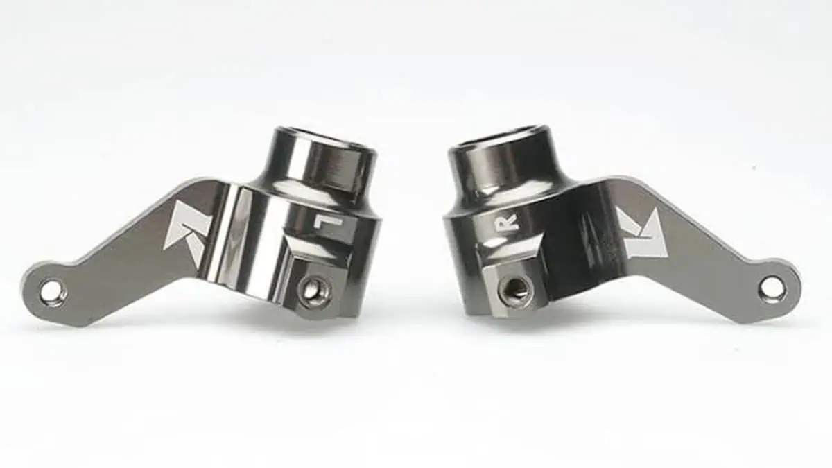
Automotive metal-part marking context. The marking area, surface geometry and locating method should be reviewed together before the fixture and machine configuration are finalized.
Orientation marks and other visible identifiers may appear simple, but their final position, contrast and durability still need to be confirmed on the actual production part.
What Is Marked
What Is Usually Marked on Auto Parts?
Automotive parts may carry human-readable identification, machine-readable codes, variable production data or customer-defined specification marks. The content, size and position of the mark affect resolution, field size, fixture accuracy, data handling and validation.
Serial Numbers, Part Numbers and Batch Codes
For human-readable identification, define the smallest character size, line count, available area and required position tolerance. If the mark is used for production or recall records, also define how the variable data is generated and checked.
Data Matrix, QR and Machine-Readable Codes
For Data Matrix and other machine-readable codes, define code size, data content, available marking area and the intended reading conditions. A production reader answers whether the code can be decoded under the real lighting, distance and angle used on the line. Formal symbol-quality grading is a separate requirement and should follow the method and acceptance grade specified by the customer or applicable standard.
For laser direct part marking (DPM) and other directly marked 2D symbols, formal verification may use a DPM-specific method such as ISO/IEC 29158 together with the relevant 2D symbol-quality specification. Do not assume a minimum grade unless it is defined by the customer, drawing or program requirement.
Mark Size, Position and Available Marking Area
A code that fits easily on a large flat face may become difficult on a small fastener head, narrow flange or recessed pocket. Confirm the usable area, edge clearance, orientation and whether the mark must stay within a specified positional tolerance.
Variable Data, Traceability and Production Requirements
If each part receives unique data, define the data source and handoff method before finalizing the station. Projects may range from operator-entered serial numbers to barcode-driven jobs, PLC communication or a wider traceability system. The marking station should implement the customer’s data requirement rather than invent the traceability rule. For PLC, MES, database and code-reading integration, continue to Traceability, PLC, MES & Data Integration.
Mark requirement before machine model. Human-readable text, DPM codes, variable data and position tolerance create different demands on field size, resolution, data handling and verification. Define those inputs before comparing wattage or equipment models.
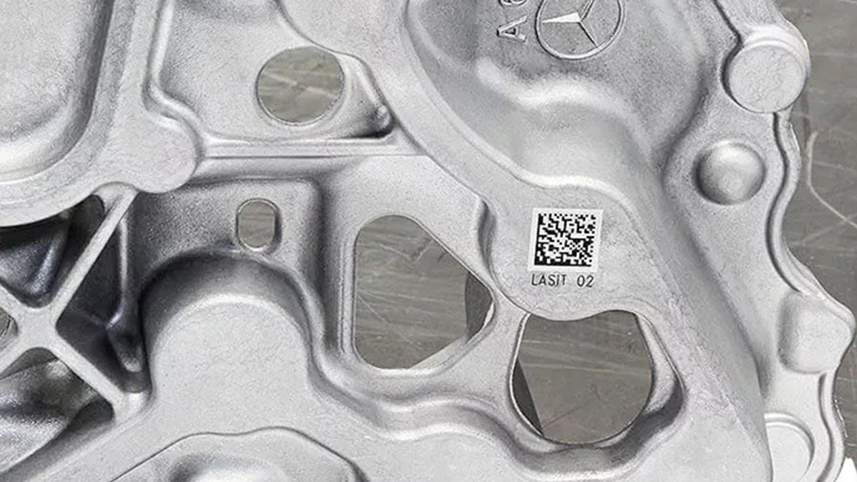
Direct-part code marking. A 2D code on an automotive component must fit the available surface, remain inside the required position tolerance and be readable under the intended production conditions.
Operational decoding and formal barcode verification are separate checks; the required acceptance method should be defined by the customer or applicable specification.
Result Variables
What Determines Laser Marking Results on Auto Parts?
The part name alone is not enough to predict the result. The actual alloy or formulation, finished surface, feature size, geometry and downstream process determine what can be produced and how stable the process will be.
| Variable | Why it matters | What to confirm before testing |
|---|---|---|
| Base material and grade | Different alloys and formulations can respond differently to the same wavelength and pulse conditions. | Material family, grade where known, and whether the production lot can vary. |
| Coating, plating, oxide or paint | The laser may be changing the surface layer, exposing the substrate or interacting with both. | Final surface treatment, approximate layer condition and whether the mark may remove or alter that layer. |
| Roughness, machining marks, oil and contamination | Surface texture and residues can change visible contrast, code-cell uniformity and process consistency. | Use representative production surfaces, including normal cleaning and handling condition. |
| Heat treatment and process stage | Scale, color, hardness and surface chemistry may change before or after heat treatment. | Whether marking occurs before or after heat treatment and what downstream steps follow. |
| Mark size and feature density | Small characters and dense 2D codes demand tighter control of spot size, field size, focus and positioning. | Minimum character size, code dimensions, data capacity and available marking area. |
| Curvature and height variation | Focus changes across the mark area can reduce contrast, sharpness or code consistency. | Highest and lowest surface points, mark width, diameter and accessible marking angle. |
| Part-to-part position variation | A stable laser process can still produce misplaced or incomplete marks if the part is not located repeatably. | Locating datum, fixture repeatability, incoming orientation and loading method. |
| Downstream cleaning, coating and wear | A mark that looks acceptable immediately after marking may change after washing, coating, abrasion or service exposure. | Which downstream conditions must be included in acceptance testing. |
Need material-specific response guidance? Use the relevant Metals, Plastics or Coatings & Surface Treatments guide when the main uncertainty is how the actual material or surface responds. This application page stays focused on the auto-part task, geometry, production conditions and validation path.
Target Result
What Marking Result Should You Target on Auto Parts?
Define the result in terms that can be inspected or tested. “Permanent laser mark” is too broad: a readable Data Matrix, a high-contrast part number, shallow engraving and controlled coating removal are different targets.
| Target result | Typical objective | Acceptance should define |
|---|---|---|
| High-contrast human-readable identification | Make serial numbers, part numbers, dates or specifications easy to read. | Character size, legibility, contrast expectation, position and cosmetic limits. |
| Machine-readable DPM code | Create a directly marked Data Matrix or other 2D symbol that can be decoded reliably in the intended process. | Code size, reader conditions, verification method if required, position and consistency across parts. |
| Shallow engraving or controlled material removal | Create a physical mark where visible depth or resistance to surface wear is part of the requirement. | Allowed depth or surface change, edge quality, readability and any dimensional or fatigue-sensitive limits defined by the part owner. |
| Coating or layer contrast | Use the difference between a treated surface and the underlying layer to create the mark. | Whether the layer may be removed, acceptable substrate exposure, contrast and downstream corrosion or appearance requirements. |
| Minimal surface or thermal disturbance | Prioritize fine identification while limiting unwanted discoloration, melting or material removal. | Allowed heat tint, texture change, removal, edge effect and functional-surface restrictions. |
Do not choose the machine from the material name alone. First define the acceptable result, then test the laser route that can achieve that result on the actual finished surface without creating an unacceptable side effect.
Geometry, Positioning & Loading
How Do Part Geometry, Positioning and Loading Affect the Setup?
The station must place the marking surface in a repeatable optical position. Check access, locating accuracy, surface-height variation and how parts arrive at the station, because loading method can change fixture design, cycle time and the need for vision or automation.
Flat Parts and Simple Marking Surfaces
Flat, accessible surfaces are the simplest case. A standard marking setup may be enough, but the fixture still needs a reliable locating datum if mark position matters.
Shafts, Pins and Other Cylindrical Auto Parts
A cylindrical part does not automatically require a rotary axis. If the mark is placed on a flat end face or a narrow OD area within the usable focus range, a fixed setup may work. Rotary marking becomes relevant when the mark wraps around the circumference or the required marking width exceeds what can be handled on one tangent area. For circumferential and OD setup methods, see Rotary & Cylindrical Marking.
Curved, Recessed and Height-Variable Surfaces
Curved housings, pockets and forged surfaces can create focus variation or block line of sight. Check the highest and lowest points in the mark area, lens clearance and whether a 3D marking method or a different fixture orientation is required. For height compensation across curved surfaces, see 3D Curved-Surface Marking.
Multi-Side Parts and Variable Part Position
For parts that need marks on several faces, decide whether the operator will reposition the part, a fixture will index it, or an automated station will move the part. If incoming orientation varies, Vision Positioning may be more important than higher laser power. For indexed handling or multi-station projects, evaluate Automatic Marking Cells.
Locating Datums, Repeatability and Marking Access
Before approving a fixture, confirm the locating datum, part-to-part position variation, clamping repeatability, laser-head clearance and loading direction. A mark that looks correct on one manually positioned sample may still fail in production if the fixture cannot repeat the same location.
Loading Method and Production Flow
Manual loading, trays, nests, feeders, conveyors and robot handling create different positioning and cycle-time conditions. Define how the operator or automation presents the part, whether orientation can vary, how rejects are handled and whether marking must be synchronized with other equipment.
Manufacturing Process
When Should Auto Parts Be Laser Marked in the Manufacturing Process?
The same mark can perform differently depending on when it is applied. Before choosing the marking station, check every process that happens before and after laser marking.
Laser Marking Before or After Machining
Do not place the mark on an area that will later be cut, ground or machined away. If machining changes the final surface condition, evaluate the mark on the finished surface rather than assuming a pre-machining test will represent production.
Laser Marking Before or After Heat Treatment
Heat treatment can change scale, color, hardness and surface condition. If marking is performed before treatment, validate the final result after the complete thermal process. If marking is performed after treatment, evaluate the actual treated surface.
Laser Marking Before or After Coating, Plating or Painting
A later coating can cover, reduce or change the appearance of a mark. Marking after anodizing, plating, painting or another surface treatment may require a different process than marking bare metal. Use the final production surface for sample testing whenever possible.
Will Cleaning or Assembly Affect the Final Mark?
Check washing, solvents, oil, abrasion, shot blasting, assembly contact and any other downstream exposure relevant to the part. Where long-term durability is required, the acceptance criteria should come from the customer or applicable specification and be tested under representative conditions.
Laser Route
Which Laser Route Should Be Tested First for Auto Parts?
The first test route should follow the finished material and the target result. For common metal parts, fiber is usually the starting family; MOPA fiber or another wavelength is evaluated when the required contrast, feature control or surface response cannot be established with the first route.
Standard Fiber for Many Metal Auto Parts
For many bare, machined, oxidized or otherwise laser-responsive metal surfaces, a fiber laser is the first family to evaluate for serial numbers, text, logos and direct-part codes. The sample still needs to confirm contrast, surface effect, feature quality and cycle time on the actual alloy and finished surface. Once validated, compare fiber laser marking machines at the product-family level.
MOPA Fiber When Pulse Control Changes the Process Window
MOPA is still a fiber-laser route, but its wider pulse-control range can be useful when the test needs more flexibility for contrast tuning, fine features or reduced unwanted thermal loading. It should be selected because the sample result benefits from that control range, not simply because the source is more configurable.
UV or Another Wavelength for Plastics, Coatings or Sensitive Surfaces
UV or another laser family may be evaluated when a polymer, coating or heat-sensitive surface responds poorly to the initial fiber route, or when the required feature and surface effect demand a different interaction. Material-specific behavior should be checked in the relevant Plastics or Coatings & Surface Treatments guide and confirmed on representative parts.
Use the Sample Result to Decide Whether to Change Route
If the first route gives weak contrast, unstable code cells, excessive removal, unwanted heat effect or an unacceptable surface change, do not solve the problem by increasing power alone. Recheck the target result, process window and material condition, then evaluate a different pulse regime or laser family when the evidence justifies it.
Failure Modes
What Are the Common Risks and Failure Modes?
A poor result is not always caused by the laser source. Surface variation, focus, code design, fixture repeatability, process position and complete station cycle can all create failures that appear only when the application moves from a bench sample to production.
| Failure symptom | Likely areas to investigate | What to verify |
|---|---|---|
| Weak or inconsistent contrast | Material variation, coating condition, roughness, oil or an unstable parameter window. | Representative surface condition, process repeatability and whether the target effect is realistic for that surface. |
| Data Matrix reads intermittently | Code size, cell quality, focus, contrast, surface texture, reader angle or lighting. | Operational decoding across multiple parts and formal verification when the project requires it. |
| Mark position varies from part to part | Weak locating datum, fixture play, inconsistent loading or variable incoming orientation. | Fixture repeatability, clamping, loading direction and whether vision is required. |
| Curved or recessed marks lose sharpness | Focus variation, blocked access, excessive marking width on a curved surface or unsuitable orientation. | Surface-height range, working distance, usable field and whether rotary or 3D capability is justified. |
| Excessive removal, heat tint or unwanted surface change | Process window too aggressive for the target result or surface condition. | Allowed depth, texture, discoloration and functional-surface limits before changing power or speed. |
| Coating removal exposes the wrong layer | Layer thickness variation or a target result that was not defined clearly enough. | Finished coating stack, acceptable substrate exposure and downstream appearance or corrosion requirements. |
| Mark changes after cleaning, heat treatment or coating | The test was performed at the wrong manufacturing stage or without representative downstream exposure. | Production process position and acceptance after the downstream steps that matter. |
| Sample looks good but production misses cycle or repeatability | Only laser-on time or a best-case manually positioned part was evaluated. | Full load-locate-mark-read-reject-unload cycle and repeated results across representative parts. |
Failure-mode review prevents unnecessary machine upgrades. A rotary axis, 3D head, vision system or higher-output source should solve a verified geometry, positioning, process-window or cycle-time problem—not compensate for an undefined requirement.
Sample Acceptance
How Should Auto-Part Samples Be Tested and Accepted?
A useful sample test starts with the acceptance requirement, not the laser settings. Test representative parts in the production surface condition, then check the mark, downstream durability, repeatability and complete cycle before using the result as the basis for production equipment.
Sample-Test Sequence Before Production Release
- Confirm the part and surface. Record the material grade, coating or treatment, roughness and marking location.
- Confirm the mark. Define text, code type, size, data content and the acceptable visual result.
- Check geometry and fixturing. Confirm access, focus variation, locating datum and repeatability.
- Run an initial process window. Test a suitable laser and parameter range on representative parts.
- Inspect the result. Check appearance, position, readable content and any surface effect that matters to the application.
- Validate production requirements. Test operational code reading, downstream durability and real cycle time where these are part of acceptance.
- Confirm the production-release basis. Repeat the test across representative parts and record the accepted surface condition, mark criteria, reader conditions, downstream checks and complete-cycle expectation that the final station must reproduce.
Mark Quality, Contrast and Code Readability
Check the actual mark for legibility, contrast, position and consistency. For machine-readable codes, use the intended production reader under representative lighting, distance and angle conditions. A code that reads once under ideal bench conditions is not enough evidence for a production station.
Data Matrix Verification and Reader Conditions
A production reader and a barcode verifier answer different questions. The reader confirms operational decoding. A verifier is used when the project requires formal symbol-quality grading. For directly marked 2D symbols, the applicable DPM verification method and minimum grade should be defined by the customer or relevant specification.
Durability Through Downstream and Service Conditions
Define the exposures that matter to the real part: washing, solvents, abrasion, corrosion environment, temperature or later surface processing. Required mark life is a customer acceptance criterion and should be confirmed under representative conditions rather than assumed from the laser type.
Repeatability and Real Production Cycle Time
Measure the complete production cycle: load, locate, mark, read or inspect, reject if required, and unload. Repeat the test across multiple parts to check fixture repeatability and process stability before using the result for equipment selection.
Laser safety & process fumes. Safety requirements depend on the final laser source and complete machine configuration. Enclosures, access points and interlocks should be evaluated as part of the finished laser product. Laser processing can also generate particles or vapors from coatings, plastics, oils or contamination, so ventilation or extraction should be assessed for the actual material and process.
Zhuorui Laser assembles, configures and tests complete laser marking machines, and real-part sample marking is used to reduce application uncertainty before the final configuration is confirmed. To arrange a test, send the part information and acceptance requirements through Contact Us.
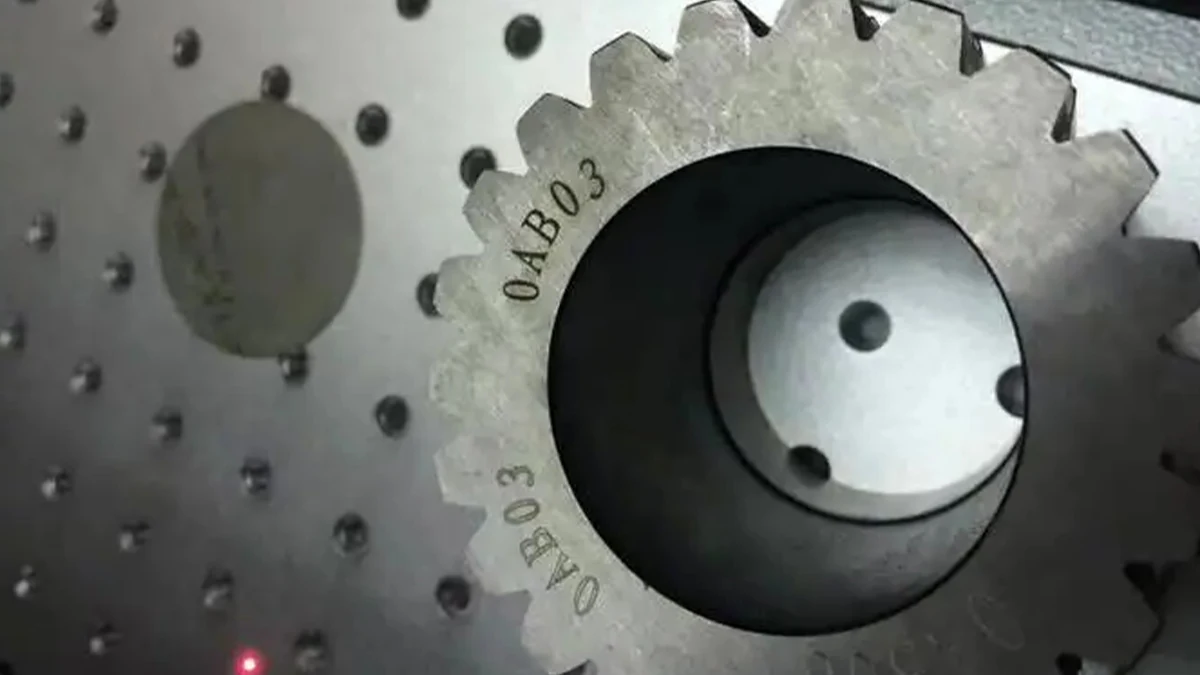
Configuration Logic
How Do Sample-Test Results Determine the Final Machine Configuration?
The machine should be the consequence of the validated task. Use the sample and production findings to decide the laser family, marking field, fixture, motion, positioning, safety, extraction and automation requirements instead of selecting options in advance.
| Test or production finding | What it tells you | Configuration consequence |
|---|---|---|
| The tested fiber route produces the required contrast or code quality without unacceptable surface change. | The basic laser-material interaction is suitable. | Keep fiber as the laser family candidate and size the remaining machine around field, fixture and production needs. |
| The required result needs a wider pulse-control window or the first fiber setup creates unwanted thermal or surface effects. | The process window, not just nominal power, needs adjustment. | Evaluate MOPA fiber or another validated source route before freezing the machine. |
| Fine text or a dense DPM code only passes within a smaller usable field. | Resolution and field-size trade-off is affecting mark quality. | Select the lens and marking field from the validated feature size rather than choosing the largest field by default. |
| Surface height variation causes loss of focus across the required mark area. | A fixed-focus setup cannot reproduce the accepted result over the full geometry. | Reorient the fixture or evaluate 3D marking when the measured height range justifies it. |
| The mark must wrap around a shaft, pin or other cylindrical OD. | The required marking width extends beyond a stable tangent-area mark. | Add a rotary axis and fixture that control diameter, concentricity and orientation. |
| Incoming orientation or mark position varies too much for a fixed fixture. | Part presentation is the limiting factor. | Improve the locating fixture or evaluate vision positioning if the actual variation requires automatic correction. |
| Manual load-locate-mark-read-unload cannot meet the target cycle or repeatability. | The station-level process, not laser-on time, is limiting throughput. | Evaluate trays, feeders, indexing, conveyor handling or a project-based automatic marking cell. |
| Each part requires variable data, reader confirmation or plant-system handoff. | The marking station must participate in the customer’s data workflow. | Define barcode input, PLC/MES/database communication, read-back and reject logic as part of the configured system. |
| The process generates significant particles or vapors from oil, coatings or polymers. | Process emissions are part of the station design. | Evaluate extraction, enclosure and safe access together with the final source and workpiece. |
Configuration approval should be traceable to an observed requirement. Every added option—rotary, vision, 3D, automation, data integration, enclosure or extraction—should answer a specific result, geometry, positioning, cycle, data or safety condition found during evaluation.
FAQ
Common Questions About Auto Parts Laser Marking
Can laser marking be used on my automotive part?
Many common automotive metal parts are candidates for fiber or MOPA laser marking, but suitability depends on the exact alloy, coating, surface state, required contrast or depth, and downstream processing. Plastics and coated components may require a different laser family. The reliable way to confirm feasibility is to test a representative part in its production surface condition.
What laser marking machine do I need for auto parts?
Start with the marking task rather than wattage. Define the part, finished material and surface, marking content, target result, geometry, loading method and production rate first. Then use sample-test results to determine the laser family, field size, fixture and whether rotary, vision, 3D, extraction or automation is actually required. A standard machine may be enough for simple flat parts; more complex parts need configuration around the validated task.
Should auto parts be laser marked before or after coating or heat treatment?
It depends on the production sequence and the final mark requirement. Later machining, heat treatment, coating, plating, painting or aggressive cleaning can alter or cover an earlier mark. When possible, test the mark in the same process position and surface condition that will be used in production, then inspect it after the downstream steps that matter.
Do shafts and cylindrical parts always need a rotary axis?
No. A shaft marked on its end face or on a narrow tangent area may be handled without rotation. A rotary axis becomes useful when the mark must wrap around the circumference or cover a wider OD area while maintaining focus and positioning. The decision depends on the mark width, diameter, allowable distortion and fixture design.
How are Data Matrix codes checked after laser marking?
First confirm that the intended production reader can decode the code under representative lighting, distance and angle conditions. If the customer requires formal symbol-quality grading, use the applicable verification method and acceptance grade. Operational reading and formal verification are different checks, so the requirement should be defined before the machine is finalized.
How do I confirm the mark will survive my production process?
Define the exposures that matter to the actual part, such as washing, solvents, abrasion, corrosion environment, heat or later surface processing. Then test representative marked parts through those conditions and inspect them against the customer’s acceptance criteria. Mark durability should be validated for the application rather than assumed from the laser type.
What information should I send for an auto parts laser marking test?
Send a drawing or clear photos, material grade, coating or surface treatment, marking content, available marking area, target mark effect, required production rate and any reader, verification, automation or data-integration requirement. If possible, also provide representative parts for testing. These inputs allow the application and machine configuration to be reviewed more accurately.
Next Steps
Start Your Auto Parts Laser Marking Evaluation
Send us the part drawing or photos, material and surface condition, marking content, available marking area and target production rate. If machine-readable codes are required, include the code size, data format and any reader or verification requirement.
We can use those inputs to review the application, determine whether sample testing is needed and define the appropriate standard or custom machine configuration.
Prepare for a faster technical review: