
Laser Marking Machine Applications · Automotive & EV
VIN and Chassis Laser Marking for Vehicle Frames
Vehicle manufacturers and chassis suppliers use VIN laser marking for frame identifiers and related permanent marks on chassis rails, structural members, body areas and nameplates. The key question is what your program requires: mark content and location, applicable regulatory or OEM requirements, material and surface condition, chassis geometry, target permanence or depth, and the production rate you must hold.
Request a Quote Browse VIN Marking
- VIN content, location and format
- Compliance and tamper-resistance
- Depth or permanence acceptance criteria
- Frame material and surface condition
Quick Answer
What VIN and Chassis Marking Involves
The decision is not whether a laser can mark a VIN, but what your vehicle program requires: the mark content and location, the applicable regulatory or OEM acceptance criteria, the frame material and geometry, the required permanence or depth, and the production rate you need to hold.
Yes — VIN and chassis marking is a well-established laser application. Vehicle manufacturers and chassis suppliers use laser marking to apply VINs, frame identifiers and related marks to chassis rails, structural members, body areas and nameplates, because the process is non-contact, permanent and repeatable.
For VIN/chassis projects, first define the marking requirement and acceptance criteria. Then use the relevant material guidance to review substrate behavior, and move to Solutions or Products only when you need to resolve integration method or machine configuration.
VIN Format and Character Requirements
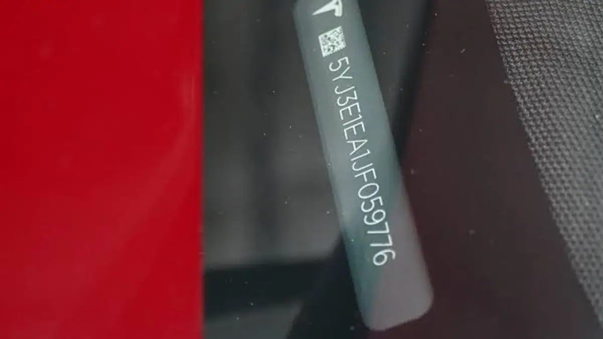
A VIN is a standardized vehicle identification code, commonly 17 characters under ISO 3779. For marking work, the practical inputs are the required character set and size, mark location, durability or permanence criteria, and any market- or OEM-specific acceptance requirements. Those requirements come from the applicable vehicle program and regulation, not from the laser marking machine alone.
Where VIN Marks Are Applied
- Chassis rails and frame members — longitudinal rails and cross-members on body-on-frame vehicles; marks are often placed on surfaces that are difficult to reach and modify, which supports tamper-resistance.
- Structural members of unibody vehicles — body-in-white and underbody structural areas where the VIN reference must survive the vehicle life.
- Nameplates and labels — VIN plates mounted in the cabin or door area, which may be laser-marked as part of plate production.
Where exactly a VIN must appear is defined by the regulations of the market where the vehicle is sold. The marking equipment must reach the intended location, hold position and repeat the same mark at the required quality across the production run.
What Is Usually Marked on Vehicle Frames and Chassis Parts?
Distinguish the mark type before choosing the process: a statutory or primary VIN, a chassis or frame identifier with a separate format, a secondary or confidential identifier used by the manufacturer, or an internal traceability mark. Confirm which one applies to the vehicle program before setting character, permanence and validation requirements.
How VIN Marking Differs from General Part Serial Numbers
A general serial or part number on a component is mainly a traceability mark. A statutory or primary VIN can carry additional requirements for format, location, legibility and resistance to alteration, depending on the market and vehicle program. That makes VIN/chassis marking a separate application task rather than just another component serial-number job.
For general automotive part serial numbers and 2D codes, see Auto Parts Laser Marking. For the broader automotive task view, see Automotive & EV Applications.
Application Purpose
Why Are VIN and Chassis Marks Required?
VIN and chassis marking is not only about putting characters on metal. The mark has to serve a defined identification, compliance or traceability purpose and remain usable under the conditions required by the vehicle program.
- Vehicle identity — Apply the primary VIN or another required vehicle/frame identifier in the specified location and format.
- Regulatory or OEM compliance — Meet the applicable rules for character structure, location, legibility, permanence or resistance to alteration.
- Manufacturing traceability — Link the frame or body to the correct production record, vehicle build or internal identifier when the program requires it.
- Service and lifecycle identification — Keep an identifier readable for inspection, registration, service or vehicle-history processes over the required service life.
- Secondary or confidential identification — Support manufacturer-defined secondary identifiers where these are part of the vehicle program.
- Error prevention — Make sure the correct identifier is applied to the correct vehicle or chassis before the part moves to the next production stage.
Start with the mark purpose. A statutory VIN, a manufacturer secondary identifier and an internal traceability mark can use different rules for content, location, permanence, verification and production data handling. Do not treat them as the same marking task.
Compliance
Compliance and Tamper-Resistance Considerations
VIN requirements vary by destination market and vehicle category. Confirm the current rule or OEM specification first, then translate it into marking inputs such as VIN structure, location, character geometry, permanence and any required validation method.
Regulatory Frameworks to Check for Your Destination Market
Use the current rule that applies to the vehicle program. ISO 3779:2009 defines VIN content and structure and remains current after its 2024 review. In the United States, current NHTSA VIN requirements are contained in 49 CFR Part 565. For relevant EU vehicle categories, Commission Implementing Regulation (EU) 2021/535 includes requirements for VIN location and inalterability. Always verify the version and scope that apply to your destination market; compliance is determined at the vehicle/program level, not by the marking machine alone.
VIN Character Size and Typeface Requirements
Character rules are market- and vehicle-specific. For example, U.S. Part 565 requires capital sans-serif VIN characters and, for specified passenger cars, multipurpose passenger vehicles, low-speed vehicles and trucks at or below 4,536 kg GVWR, the VIN visible through the vehicle glazing must use characters at least 4 mm high. Do not carry that value over to another vehicle category or market without checking the applicable rule.
Tamper-Resistance and Mark Permanence
Resistance to removal or alteration is an acceptance objective, not a universal formula of “depth plus location.” Mark depth, location, substrate, accessibility and the marking method can all contribute. If the applicable regulation or OEM/customer specification defines a minimum depth or a specific tamper-resistance test, use that as the acceptance criterion. If it does not, establish the required permanence and verification method for the actual vehicle program and confirm the result on real parts.
Target Result
What Marking Result Should You Target on VIN and Chassis Parts?
A successful VIN/chassis mark is not defined by depth alone. The target is the complete accepted result: correct content and location, readable character geometry, the required permanence or resistance to alteration, consistent quality across the real marking area, and no unacceptable effect on the part or downstream process.
- Correct content, format and location — The right identifier must be applied to the right part in the position defined by the vehicle program.
- Legible character geometry — Character height, spacing, edge definition and overall readability must remain within the applicable acceptance criteria.
- Permanence or inalterability — The finished mark must meet the program’s required resistance to removal, alteration or environmental exposure.
- Specified depth when required — If a regulation or OEM/customer specification defines a minimum depth, that value becomes a measured acceptance criterion.
- Consistent result across the marking area — Depth, edge quality and appearance should not vary unacceptably because the rail is curved, tilted or presented at a different height.
- Acceptable effect on the part — Heat input, coating removal, surface damage and corrosion-protection implications must stay within the vehicle or process requirement.
What Determines the Result?
- Material and grade — High-strength steel, carbon steel, aluminum, stainless steel and other frame materials respond differently to the same laser strategy.
- Surface condition — Coating, plating, scale, oil, oxidation and whether the mark is made before or after paint change absorption, contrast, edge quality and the amount of material that must be removed.
- Laser energy strategy — Pulse behavior, frequency, scan strategy and controlled passes affect depth, heat accumulation and edge quality; nominal power alone does not define the result.
- Focus, field and surface angle — Focal variation across a curved or tilted structural member can create uneven depth or distorted characters.
- Part positioning and fixture repeatability — A stable process window cannot compensate for a chassis that arrives at a different position or height every cycle.
- Production timing — Marking before paint, after paint, before assembly or on an assembled frame changes access, surface condition, verification and downstream corrosion considerations.
How Mark Depth Fits into the Target Result
Some VIN/chassis programs require a physical engraving rather than only a surface color change. If a minimum depth is specified, measure and validate that value on the actual part. If no explicit depth is specified, treat depth as one engineering variable used to achieve the required permanence, legibility and resistance to alteration rather than as a universal target.
Deeper engraving is commonly built through controlled passes and an appropriate pulse/energy strategy. Simply increasing nominal machine power does not guarantee a deeper or better VIN mark. Confirm depth together with character edges, heat-affected appearance, coating condition and the production cycle time.
How Frame Material and Surface Condition Change the Target
Frame materials commonly encountered in VIN/chassis marking include steel and high-strength steel, aluminum, stainless steel, galvanized steel and other coated surfaces. Grade, coating, scale, oil and whether marking occurs before or after painting can change achievable depth, edge quality, contrast and corrosion-protection considerations.
Marking timing also matters. A VIN marked before painting may be covered by the paint system, while marking after coating requires surface handling and can change contrast or edge quality. Review the effect of deep marking or coating removal on the part’s corrosion protection and subsequent processing before the process is frozen.
Geometry & Configuration
How Do Chassis Geometry, Access and Fixturing Affect the Marking Process?
Chassis and frame marking is rarely a simple flat-part job: rails are long, structural areas are curved or enclosed, and the mark location is often where the vehicle is assembled. Geometry and production flow determine the configuration you should evaluate.
| Scenario | Typical example | Configuration direction |
|---|---|---|
| Marking in place on an assembled chassis or frame | VIN on a frame rail after welding, where moving the frame is impractical | Portable / handheld or transportable marking head; fixture or guide to hold position |
| Fixed-station marking of frame components | Pre-assembly marking of rails or cross-members at a dedicated cell | Standard marking machine with a frame-specific fixture |
| Multi-side or curved structural areas | Marks on curved members or two sides of a rail | Multi-position fixture or automatic cell; see automatic loading & multi-station solutions |
| In-line marking on a moving line | VIN applied while the body or frame moves along the assembly line | Evaluate station-based or synchronized online marking options first; on-the-fly flying / online marking only when speed synchronization, encoder, focal and quality conditions are validated |
| Inconsistent positioning or orientation | Frame components arriving with variable position | Evaluate vision positioning |
Use these as starting points only. Final configuration depends on part geometry, access, production rate, positioning tolerance and integration requirements. Review marking solutions when the project needs vision, online marking or automation, and compare machine families after those application requirements are defined.
Technology Direction
Which Laser Type Is Used for VIN and Chassis Marking?
For metal VIN/chassis engraving, fiber is a common starting technology and MOPA fiber may be evaluated when wider pulse control is useful. Treat the laser family as the first screening decision only; material, surface state, target depth or permanence, heat input and sample results determine the final configuration.
| Laser family | Typical role in VIN/chassis marking | Why it is evaluated |
|---|---|---|
| Fiber (Q-switched, ~1064 nm) | Common starting point for deeper marks on most frame steels and alloys | Well absorbed by many metals; can build depth through repeated passes with controlled energy |
| MOPA fiber | Depth and contrast control, coated or heat-sensitive surfaces | Wider pulse and frequency control for managing heat input and mark consistency |
| UV / CO₂ | Not typically the first choice for deep metal VIN marks | UV is evaluated for heat-sensitive plastics, CO₂ for some non-metal surfaces — VIN frame marks are usually metal; confirm actual CO₂ wavelength per machine |
Because achievable depth depends on the material and the energy strategy, the laser family is only the first direction. Marking your actual frame material confirms what is realistic. For machine families and configurations, see fiber laser marking machines and the wider Products section.
Process Risk
What Are the Common VIN and Chassis Marking Failure Modes?
A failed result does not always mean the laser source is wrong. The defect can come from the material, surface state, focal position, fixture, data flow or production sequence. Use the failure mode to identify which part of the process should be changed before the machine configuration is frozen.
| Failure symptom | What it can indicate | What to review first |
|---|---|---|
| Depth is too shallow or varies between parts | Material or surface variation, focal shift, unstable presentation or an insufficient process window | Material/surface condition, focus, fixture repeatability, pulse/energy strategy and pass count |
| Character edges are rough or material removal is excessive | Too much local energy, an unsuitable pass strategy or poor focus | Pulse strategy, scan strategy, focus and the minimum depth actually required |
| Heat-affected appearance is too large | Excessive energy accumulation for the required result | Pulse behavior, dwell/passes, scan strategy and whether a wider-control fiber route should be compared |
| Coating burns, lifts or is removed beyond the intended area | The coating stack or marking timing is not compatible with the current process window | Coating type/thickness, before-or-after-paint process, energy strategy and acceptance limit |
| Depth or character quality changes along a curved rail | The marking surface is moving outside the stable focal range or changing angle | Fixture, part datum, working distance, surface angle and focal-management requirement |
| VIN position shifts between frames | The problem is primarily locating or presentation, not laser power | Fixture datum, chassis stop, clamping, sensor/vision requirement and loading repeatability |
| Characters are correct on a sample but inconsistent in production | Production variation was not represented in the bench test | Incoming surface variation, loading, focus, handling, cycle sequence and verification method |
| Tamper-resistance, permanence or durability acceptance fails | The selected result does not meet the program’s actual validation method | Required test method, depth/permanence target, mark location, substrate and process strategy |
| Marking time meets quality but misses takt time | The process is technically feasible but not production-feasible at the current configuration | Depth target, number of passes, source capability, handling time, positioning and station concept |
| Wrong VIN or wrong vehicle receives the mark | A data-control or identification failure | Vehicle identification, job selection, PLC/MES/database interface, trigger logic and verification/reject rules |
Production Workflow
How Does VIN Marking Move from a Sample Test into Production?
Production readiness requires more than reproducing a good sample. The station must present the correct chassis in a repeatable position, receive or select the correct identifier, execute the approved marking process, verify the result and handle failures without losing traceability.
| Production step | Question to resolve | Possible system requirement |
|---|---|---|
| Identify the vehicle or frame | How does the station know which chassis is present? | Fixture datum, sensor input, barcode/RFID or production-system identification when required by the line |
| Obtain the VIN or identifier | Is the content entered manually, selected from a job, or supplied by a production system? | Controlled job file, database, PLC/MES or other verified data source depending on the project |
| Position the marking area | Can the frame arrive at the same location, height and angle every cycle? | Mechanical fixture/guide first; vision or additional position compensation only when the real variation requires it |
| Authorize and trigger the mark | What conditions must be true before laser marking starts? | Interlocks, part-present logic, job confirmation, PLC I/O or operator confirmation as appropriate |
| Execute the approved process | Can the validated depth, permanence and character quality be held within takt time? | Frozen process window, correct marking field, source configuration and focal setup |
| Verify the result | What must be checked: content, position, character quality, depth, readability or another acceptance criterion? | Operator check, camera/vision, reader, depth measurement or scheduled quality inspection depending on the requirement |
| Handle NG / duplicate / wrong-data conditions | What happens if the mark or data fails verification? | Stop/reject logic, controlled rework rule, alarm and traceable disposition defined by the vehicle program |
| Store a production record | Does the customer need a record that the correct VIN was marked and accepted? | Optional logging, time stamp, result record or production-system feedback when required |
Do not add automation by default. A stable fixed station with a mechanical datum may be the simplest correct solution. Vision, PLC/MES communication, automatic verification or moving-line synchronization should be added only when the real production variation, takt time or traceability requirement justifies them.
Safety, Extraction and Workstation Controls
Safety must be evaluated for the complete marking system. Fiber marking commonly uses invisible near-infrared radiation around 1064 nm. An open or unenclosed setup can expose hazardous laser radiation and requires controls appropriate to the accessible emission, such as a controlled area, suitable eye protection and fume extraction. A properly interlocked protective enclosure can reduce accessible emission, but an enclosure alone does not automatically establish a Class 1 system; classify and verify the complete machine and operating condition. See the OSHA laser-safety guidance for the general enclosure and hazard-control principle.
Before Production
What Must Be Validated on Real Parts
Confirm depth or permanence, character legibility, resistance to removal/alteration, durability and cycle time on the actual frame material and geometry before production. These results depend on the part and process conditions, so sample validation is the correct acceptance step.
- Material and surface state — Alloy or grade, coating, plating, oil or scale on the marking area.
- Depth / permanence and character size — Use the minimum depth only when the applicable regulation or OEM/customer specification explicitly requires one; otherwise define the permanence or tamper-resistance acceptance method that must be demonstrated on the marked part.
- Character legibility — Confirm the required character form, size, spacing and edge quality for the applicable program rather than assuming one market rule applies globally.
- Tamper-evidence — How the mark behaves under the removal/alteration tests your requirement defines.
- Durability — Resistance to wear, corrosion, solvents and the environmental exposure of the vehicle life.
- Cycle time — Marking time plus positioning, verification and handling in your real production flow.
Zhuorui Laser assembles, configures and tests complete laser marking machines. For a VIN/chassis application review, send the actual material or part, surface condition, mark content, applicable requirement and production target through Contact Us so the marking direction and sample-test scope can be evaluated.
Configuration Decision
How Do Sample-Test Results Determine the Final Machine Configuration?
The final machine should follow the evidence from the sample and production test. First identify why a result passes or fails, then convert that finding into a laser, fixture, motion, data, verification, extraction or safety requirement. Do not select features only because they are available.
| Test or production finding | Engineering interpretation | Configuration direction to evaluate |
|---|---|---|
| Required depth and character quality are achieved with acceptable cycle time | The tested laser/process window is technically suitable | Keep that laser family and size the final machine around the actual marking field, access, fixture and production interface |
| Depth is achievable but cycle time is too long | The result is feasible but the current process window is not production-feasible | Re-evaluate source capability, process strategy and handling time; do not assume nominal power alone is the answer |
| Q-switched fiber reaches depth but heat/coating effects are unacceptable | More pulse-control flexibility may be useful | Compare a MOPA fiber route on the same material and acceptance criteria |
| Quality changes with rail height, curvature or surface angle | Focus and presentation are limiting repeatability | Improve the fixture and datum first; evaluate height/focus-management or multi-axis handling only if the measured geometry requires it |
| Assembled chassis cannot be presented to a standard bench machine | Access and machine structure are the limiting factors | Evaluate a portable/transportable marking head or a dedicated station around the real chassis position |
| Part location varies too much for a fixed datum | Positioning variation is limiting the process | Improve mechanical locating first; add vision positioning when real residual variation justifies it |
| Fixed presentation is stable and repeatable | Additional vision may not add decision value | Prefer the simpler fixture-based configuration unless another verification requirement needs a camera |
| Line takt cannot be met because positioning or handling dominates the cycle | The bottleneck is the station workflow rather than only the laser mark time | Evaluate automatic loading, indexed station or line integration; use synchronized/flying marking only when motion conditions are validated |
| VIN content must come from a production system | Data control becomes part of the marking system | Add the required PLC/MES/database interface, job control, trigger logic and result feedback defined by the project |
| Automatic content or position verification is required | Acceptance cannot rely only on the operator | Evaluate camera/vision or reader-based verification matched to the actual character/inspection requirement |
| Fume or particulate generation is significant in the accepted process | Extraction is part of the production configuration | Specify local extraction and filtration appropriate to the actual material/coating and workstation |
| An open setup does not meet the site’s laser-safety controls | The complete workstation requires a different safety architecture | Evaluate enclosure, interlocks, controlled access and other safeguards based on the complete-system risk assessment; enclosure alone does not establish Class 1 |
The output of the test should therefore be more than a marked sample. Record the accepted mark result, material and surface state, process window, marking time, fixture/positioning condition, inspection method and any data or safety requirements. Those findings become the basis for the final machine and station specification.
FAQ
Common Questions About VIN and Chassis Marking
Can a VIN be marked with a laser?
Yes. VIN and chassis marking is a well-established laser application for frame rails, structural members, body areas and nameplates. The practical question is not whether a laser can mark, but whether your depth, character and tamper-resistance requirements are achievable on your frame material and geometry — which is confirmed on real parts.
How deep does a VIN mark need to be?
There is no single depth value that applies to every VIN program. If the applicable regulation or OEM/customer specification defines a minimum depth, use it as an acceptance criterion. If it does not, define the required permanence or tamper-resistance result and confirm it on the actual part. Achievable depth still depends on material, surface condition and the laser energy strategy.
Which laser is used for VIN deep marking?
Fiber lasers at ~1064 nm are a common starting point for deeper marks on frame steels and alloys; MOPA fiber offers wider pulse and frequency control for depth and heat management. The final choice depends on your material, surface state and depth requirement, and should be validated on sample parts.
Does the frame material affect the result?
Yes. Material grade, coating, scale, oil and surface condition can change achievable depth, edge quality, contrast and heat effects. Review the relevant material guidance and validate the final process on the actual frame part.
Do I need to send parts for testing?
For a production VIN/chassis project, real-part testing is strongly recommended because depth or permanence, legibility, heat effects and cycle time depend on the actual material, surface and geometry. Send the material/surface information, required character size, any specified depth or tamper-resistance criterion, and the planned production rate.
How do I request a quote for my application?
For standard equipment with clear specifications, use Request a Quote. For non-standard, automated, vision or data-integration projects, use OEM & Custom Inquiry. For general technical or after-sales questions, use Contact Us.
Next Steps
Start Your VIN and Chassis Marking Project
Define the applicable VIN requirement, frame material and surface condition, target result, mark location, production rate, positioning method, data source and verification needs. Then test the real part and use the accepted result, cycle time and production findings to determine the final laser, fixture, station, data, extraction and safety configuration.
To make a quotation faster, prepare: material and surface · product photos or drawings · marking content and size · mark location · required permanence and any specified depth · applicable VIN regulation or OEM/customer specification · marking timing (before/after paint) · production rate · automation or data needs · voltage and destination · sample quantity.