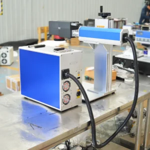
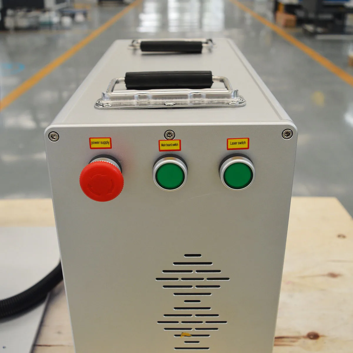
Choosing a laser marking machine becomes much easier once you stop treating the machine model as the starting point. The useful question is: what physical change must the laser create on the actual surface, and what process window will keep that result repeatable at the required production cycle? That question connects material response, pulse behavior, optics, workpiece geometry, handling, verification and the final machine structure.
Direct answer: start with the required mark and the real material/surface. Use those conditions to screen the wavelength and pulse route; size the lens from the actual mark and feature requirement; choose fixtures, rotary, vision, dynamic focus or flying only when they solve a defined geometry or motion problem; then validate the complete configuration on the real part before approving the machine for production.
Start Here: A 30-Second Laser Marking Selection Matrix
This table is a screening tool, not a final recipe. It tells you which route is usually worth testing first and what still has to be verified on the actual part.
| Starting situation | First route to evaluate | What still decides the result |
|---|---|---|
| Most bare metals and general industrial identification | Fiber | Alloy, surface finish, mark mechanism, field/spot condition and required cycle. |
| Heat-sensitive plastics, fine features or low-thermal-impact marking | UV | Polymer formulation, pigment/additive package, color, surface damage limit and feature size. |
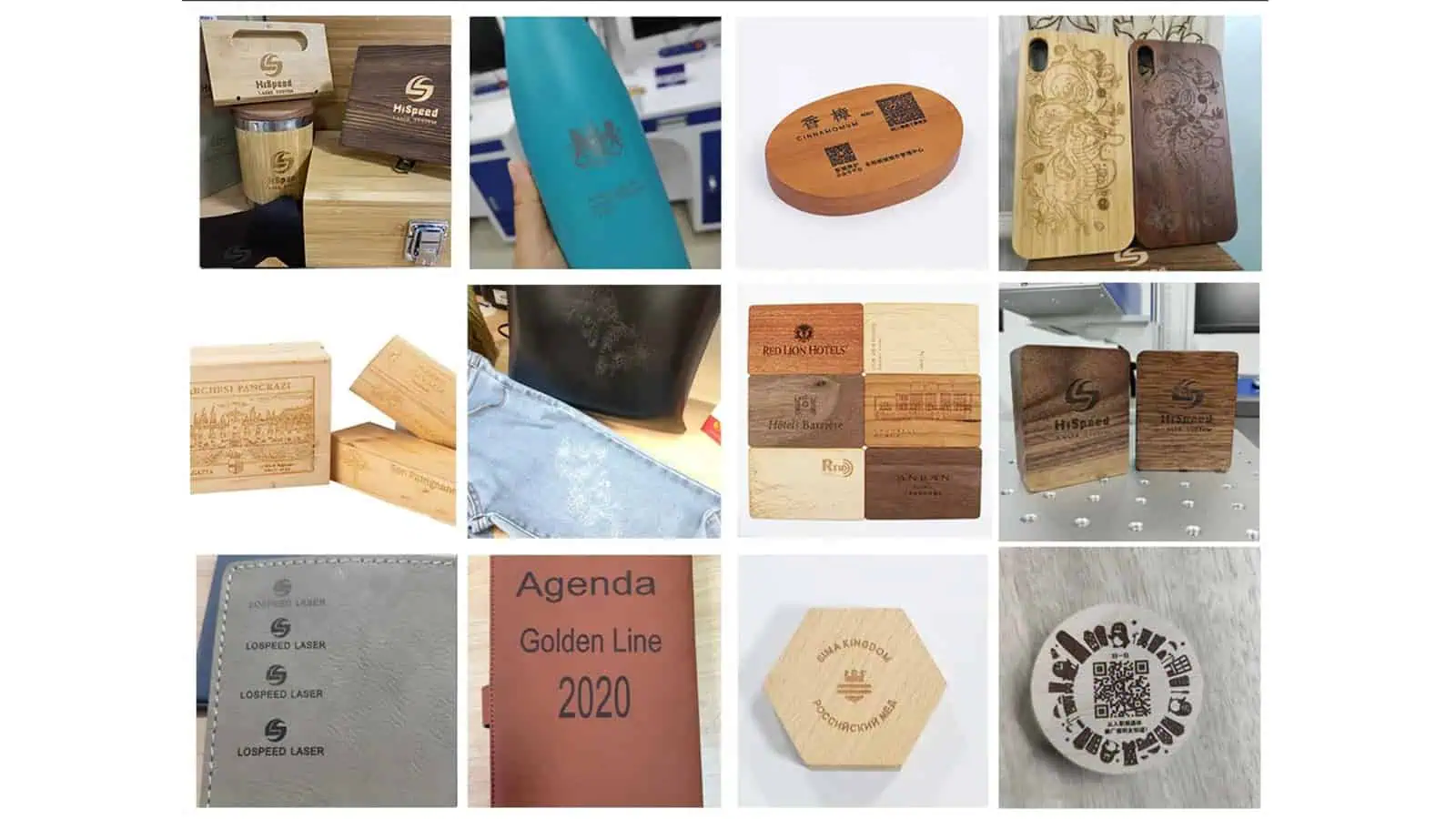
| Wood, paper, leather and many organic/non-metal materials | CO2 | Absorption, charring/melting limit, wavelength variant, extraction and desired surface effect. |
| Copper, gold, silver or other highly reflective precision work | Fiber or 532 nm Green, depending on the task | Wavelength absorption, surface condition, required material integrity and actual sample response. |
| Cylindrical or wrap-around mark | Suitable laser route + rotary | Diameter, runout, mark arc, focus tolerance and rotational positioning. |
| Meaningful height or curved-surface variation | Suitable laser route + Z compensation / dynamic focus | Actual Z range, surface geometry, optical access and acceptable spot change. |
| Part moves during marking | Suitable laser route + flying integration | Line speed, trigger timing, encoder synchronization, data timing and reject/verification logic. |
The machine is selected correctly only when the tested process, optics, motion and production workflow are considered together.
Why Laser Marking Machines Are Easy to Choose Wrong
A laser marking machine is a system, not a wattage label. The visible machine contains several interacting subsystems: laser source, beam delivery, galvanometer scanner, F-Theta or dynamic-focus optics, controller, Z positioning, fixture or motion hardware, extraction and safety structure. A change in one of these can alter the result even when the nominal laser power stays the same.
This is why two quotations that both say “30 W Fiber” can represent very different process capabilities. The source may have different pulse behavior; the lens may create a different field and spot size; the galvo and controller may have different dynamic behavior; the workholding may change focus repeatability; and the quoted cycle may or may not include loading, code generation and verification.
If a supplier can recommend a final machine from only “material + wattage,” the requirement definition is incomplete. At minimum, an industrial selection normally needs the material/surface, required mark, real mark size, workpiece geometry, positioning variation, cycle requirement and an acceptance method.
The practical selection problem is therefore not “Which model is best?” It is:
What combination of wavelength, pulse behavior, optics, motion and machine structure gives the required result with acceptable repeatability and cycle time?
The First Question Is Not Power — It Is the Mark You Need
Before choosing Fiber, UV or CO2, define what “successful marking” actually means. The same material can need very different laser conditions depending on whether the objective is surface color change, coating removal, annealing, ablation, shallow engraving, deep engraving or a machine-readable code.
| Requirement | What the engineer needs to know | Why it changes the machine choice |
|---|---|---|
| High-contrast identification | Background color, surface finish, viewing/reader condition | Contrast may come from color change, oxide formation, ablation or exposing a lower layer. |
| Deep engraving | Required depth, allowable cycle, burr/edge requirement | Material removal rate, pulse energy, spot size and pass strategy become more important than appearance alone. |
| Coating removal | Coating chemistry/thickness and substrate damage limit | The best process window may need strong absorption in the coating but limited energy coupling into the substrate. |
| QR / Data Matrix | Module size, required grade, reader, surface reflectivity | A code that looks readable to the eye may still fail a defined DPM verification method. |
| Cosmetic mark | Color consistency, edge quality, heat tint, deformation limit | Lower thermal load and a wider process window may matter more than raw throughput. |
For direct-part-marked 2D codes, the acceptance criterion should be defined before machine selection. ISO/IEC 29158:2025 provides a standardized DPM quality-test methodology with specific imaging and illumination considerations; if a customer specifies a grade, the laser process should be developed against that verification method rather than judged only by eye.
How Material–Laser Interaction Determines the First Laser Route
The reason different laser sources behave differently is not the machine cabinet. It is the interaction between wavelength, pulse behavior and the material surface.
Industrial marking commonly starts with near-infrared Fiber sources around 1.06 µm, UV systems around 355 nm, and CO2 systems in the long-wave infrared. CO2 marking sources are often 10.6 µm, but industrial variants such as 9.3, 9.6 and 10.2 µm are also used when material absorption favors a different wavelength, as shown in Coherent’s CO2 laser portfolio. The selection principle is the same: the delivered wavelength and pulse behavior must create the required physical or chemical change without unacceptable collateral damage.
KEYENCE’s Fiber / UV / CO2 comparison likewise emphasizes that wavelength changes material response and that no one laser type is universal. Treat material charts as a starting point, not a substitute for testing—surface finish, pigments, additives, coatings and the required mark can change the outcome.
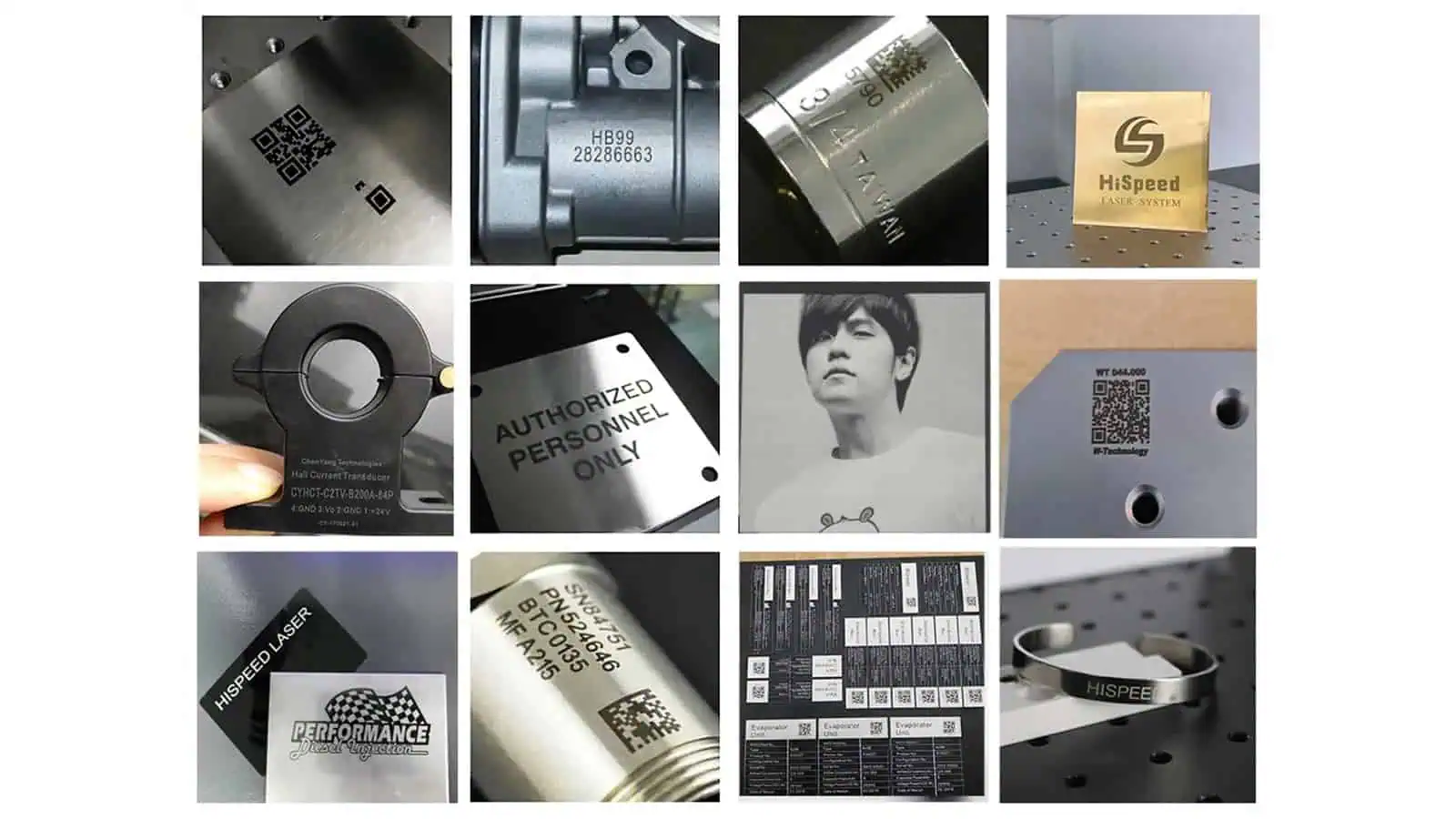
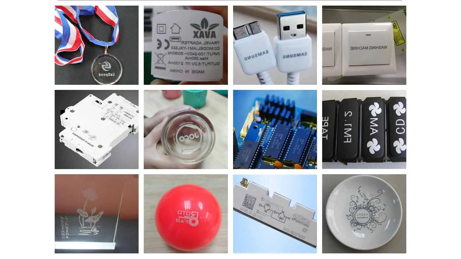
Fiber: not simply “the metal laser”
Fiber remains a strong first candidate for many industrial metal applications because 1064 nm pulsed sources can create useful thermal and ablative process windows across a broad range of metal/surface combinations. But “metal = Fiber” is still too crude. Highly reflective metals such as copper, gold and silver deserve more careful wavelength and process evaluation, while bare aluminum, anodized aluminum, stainless steel, plated parts and painted metal may rely on very different mechanisms such as oxidation, ablation, coating removal or material removal.
Within Fiber, the source architecture also matters. MOPA is a Fiber source architecture, not a fourth top-level laser category. JPT’s MOPA documentation shows independent adjustment of pulse width and repetition frequency within the source operating range, giving the process engineer another degree of freedom beyond average power.
UV: “cold marking” should not be interpreted as zero heat
UV systems are often selected for fine features and heat-sensitive materials because the short wavelength is strongly absorbed by many materials and can reduce the amount of bulk thermal input needed to create a mark. In industrial marketing this is often called “cold marking,” but the engineering interpretation should be lower thermal influence in the right process window, not “no heat is generated.”
CO2: absorption in organic and non-metal materials is the key
CO2 systems are widely used for paper, wood, leather, rubber, many packaging materials and selected polymers because these materials can absorb long-wave infrared radiation efficiently. Do not treat “CO2” as one fixed wavelength: 10.6 µm is common, while industrial sources are also available at wavelengths such as 9.3, 9.6 and 10.2 µm for applications where absorption changes with the material or film structure. The material name alone is still insufficient—transparent plastics, coated films and filled polymers can behave differently from apparently similar materials.
When 532 nm Green belongs in the screening discussion
Fiber, UV and CO2 cover a large share of conventional industrial marking work, but they are not an exhaustive list. 532 nm Green laser systems can provide higher absorption than 1064 nm Fiber on copper, gold and silver and are also used for selected white or transparent materials. Green should therefore enter the sample-test discussion when a reflective or precision-sensitive surface does not provide enough process margin with the usual Fiber or UV route. It is a route to evaluate, not a universal replacement for Fiber.
Why the Same Material Can Require Different Laser Configurations
This is one of the most important points in machine selection: the laser does not process a material name; it processes a surface under a defined energy-delivery condition.
| Same base material | Different target | What changes in the engineering decision |
|---|---|---|
| Stainless steel | Black/annealed appearance vs deep engraving | Thermal accumulation, pulse regime and scan strategy for blackening are different from repeated high-energy material removal. |
| Aluminum | Bare metal engraving vs anodized-layer marking | One process acts on the substrate; the other may mainly remove or modify a surface layer. |
| Plastic | Color change vs ablation | Resin formulation, pigment/additive package and heat sensitivity can dominate the wavelength choice. |
| Painted / coated metal | Expose substrate vs mark the coating without penetrating | The acceptable process window is defined by selectivity between coating and substrate. |
When a sample result changes dramatically after switching color, coating batch or supplier, do not immediately assume the laser is unstable. The first diagnostic question is whether the optical/thermal response of the surface changed.
Power Is Only One Part of Energy Delivery
Average power is important, but it is only one variable in a pulsed marking process. Two sources with the same nominal wattage can deliver different pulse energy, pulse duration, repetition-rate range and beam characteristics. Those differences change how the surface responds.
Peak power (simplified): Ppeak ≈ Eₚ / τ
Average-over-area fluence estimate: Favg ≈ Eₚ / A
Gaussian-beam peak fluence (using 1/e² radius w): Fpeak = 2Eₚ / (πw²) These relationships are for process understanding, not a universal parameter recipe. Actual peak power depends on pulse shape and the source operating behavior. RP Photonics gives the average-power / repetition-rate relationship for regular pulse trains, while its fluence reference explains why a Gaussian spatial profile requires a peak-fluence definition rather than simply treating the beam as a uniform illuminated disk.
Consider a simplified example. If a pulsed source is delivering 30 W average power at 100 kHz, the average pulse energy is 0.3 mJ. At 300 kHz, if the source can still maintain 30 W, the average pulse energy becomes 0.1 mJ. The machine still says “30 W,” but the energy delivered per pulse has changed by a factor of three.
Pulse duration then changes the instantaneous intensity. With the same pulse energy, a shorter pulse produces higher idealized peak power than a longer pulse. This is why pulse width and repetition rate can alter ablation, oxidation, melting and heat accumulation even when the average-power label is unchanged.
Why MOPA can matter without being “better” in every case
Many conventional Q-switched marking sources offer much less independent pulse-width control. A MOPA source can provide a broader adjustable pulse-parameter space, which can be valuable for applications where the process window is sensitive to heat input or surface response. That does not make MOPA automatically superior for every job; if a conventional Q-switched Fiber source already provides a stable, fast process, added flexibility may not justify added cost.
Buying rule: compare the process-relevant source specification, not just “20 W / 30 W / 50 W.” Ask what source type is quoted, what pulse range is available, what lens/field is used, and what cycle was achieved on the actual sample.
Marking Field, Lens, and Focus: The Optical Trade-Off Buyers Often Miss
Buyers often treat 110 × 110 mm, 175 × 175 mm or 300 × 300 mm as if they were only table-size options. They are optical choices.
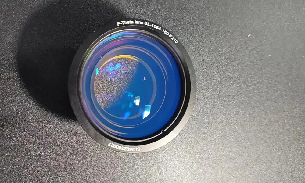
An F-Theta lens focuses the scanned beam into a flat working plane and maps scan angle to position across the field. SCANLAB’s scan-lens guidance notes that lens focal length is selected around wavelength, spot size, image-field size and working distance; short focal lengths favor compact working distances, while longer focal lengths allow larger image fields.
All else equal, a longer focal length tends to increase the focused spot size. For a collimated Gaussian beam, the ideal focused waist scales approximately with wavelength and focal length and inversely with the incoming beam radius. That means expanding the field without changing the rest of the optical system can reduce energy density and fine-feature capability.
This is why a 300 × 300 mm field is not automatically an upgrade over 110 × 110 mm. It may be exactly right for a large graphic, but unnecessary for a 5 mm Data Matrix that needs fine modules and strong local energy density.
Ask for the largest actual mark, not merely the largest workpiece. A 600 mm-long component may only need a 40 × 20 mm marking field if the mark is localized and the fixture can position it correctly.
Focus tolerance matters in real production
A sample can look perfect when an operator manually focuses one part. Production is harder: part height varies, fixtures wear, sheet flatness changes and operators load parts differently. If the process only works at one narrow Z position, the machine may be optically capable but operationally fragile.
Part Geometry Changes the Machine Before It Changes the Laser
After the laser route and optical requirement are understood, the physical machine can be selected. Machine structure should be treated as a consequence of loading, clearance, positioning repeatability, extraction and safety—not as a style choice.
| Workpiece / workflow | Likely structure question | Engineering concern |
|---|---|---|
| Small parts, repeatable manual loading | Desktop / table / split workstation | Fixture repeatability, Z travel, operator access. |
| Open-access production but better containment needed | Enclosed or semi-enclosed structure | Loading ergonomics, interlocks, extraction and final safety classification. |
| Large/heavy workpiece that cannot be moved easily | Portable / handheld / custom large-workpiece structure | Focus reference, head stability, positioning and safe operating zone. |
| Product moves continuously | Inline / flying configuration | Trigger timing, encoder synchronization, line speed and data handling. |
An enclosure is useful for containment and operator separation, but enclosure appearance alone does not establish the final laser class. IEC 60825-1:2014 applies classification and requirements to the complete laser product; components used inside a final system do not by themselves define the classification of that final machine.
CCD, 3D, Rotary, and Flying Are Solutions to Different Problems
Additional functions should be selected by diagnosing the error or motion that prevents a normal 2D stationary process from working.
| Observed problem | First solution to evaluate | What it does not automatically solve |
|---|---|---|
| Part shifts in X/Y or rotates in the fixture | CCD / vision positioning | Height variation, focus error or curved-surface compensation. |
| Mark must wrap around a cylinder | Rotary axis | Variable diameter, axial runout or complex freeform curvature. |
| Surface has meaningful Z variation | Dynamic focus / 3D | All mechanical access and surface-normal problems. |
| Part continues moving during marking | Flying marking with trigger/encoder strategy | Poor upstream positioning, unstable line speed or inadequate data timing. |
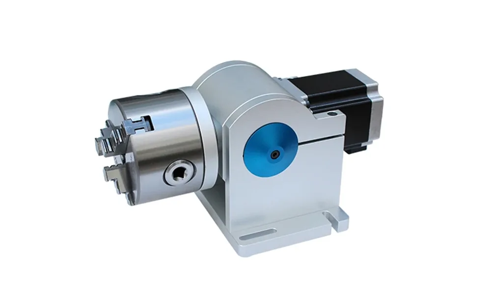
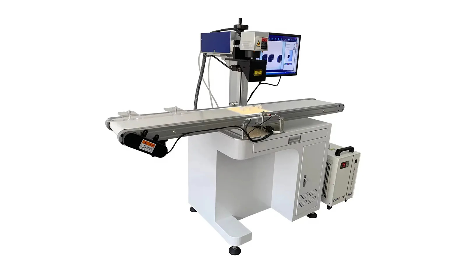
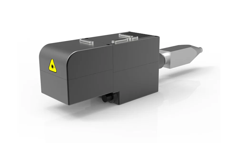
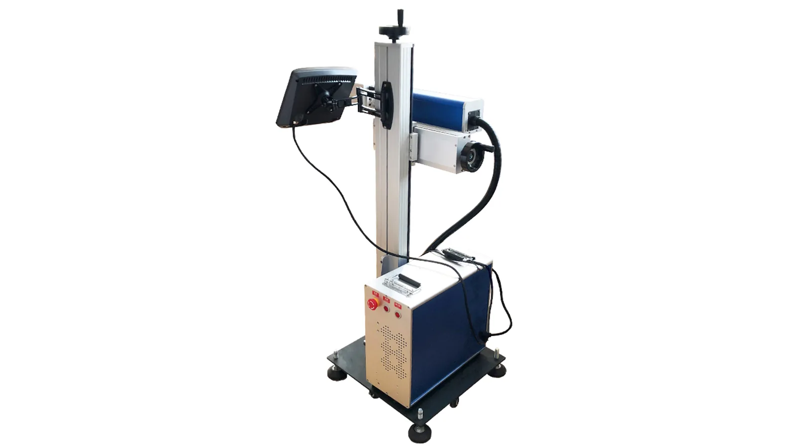
Before adding an option, identify the error source: X/Y/θ position, Z height, rotational geometry, line motion, or loading repeatability. Selecting the wrong feature can add cost without removing the real process variation.
A Good Sample Is Not Yet a Good Production Process
Supplier samples are often produced under favorable conditions: one operator, one carefully focused part, a stable fixture, no loading pressure and enough time to tune parameters. Production introduces variation.
A complete production cycle can include loading, locating, focus or height correction, data transfer, triggering, marking, code verification, unloading and conveyor indexing. Galvo scan speed is only one portion of that cycle.
| Sample-room success | Production question that still remains |
|---|---|
| One mark looks perfect | Does it repeat across consecutive parts and normal placement variation? |
| Fast laser-only marking time | What is the complete machine cycle including handling and data? |
| Good result at one focus position | How much Z variation can the process tolerate? |
| Readable 2D code | Does it meet the customer’s defined verifier/grade method? |
| No visible smoke problem during one sample | What happens to optics, enclosure and air quality during sustained production? |
For line integration, also define I/O, PLC communication, trigger source, encoder requirements, data source, serialization logic and reject/verification behavior before the machine is finalized. “Online” does not automatically mean “flying,” and “automatic” does not define how data and motion are synchronized.
What a Failed Laser Marking Test Can Tell You
A failed sample is useful only if the failure is treated as diagnostic evidence. The first response should not be “add more power.” Separate the likely error source—material/surface, focus and geometry, pulse/scan parameters, optics, positioning, contamination or production timing—then change one class of variables at a time.
| Observed symptom | First variables to investigate | How to distinguish the cause |
|---|---|---|
| Mark is dark but edges are melted, browned or heat-tinted | Heat accumulation, scan speed, repetition rate, pulse width, hatch spacing and repeated passes | Reduce thermal accumulation while holding geometry and material constant; compare edge quality and contrast rather than only the darkest result. |
| Fine characters or code modules lose definition | Focus, spot condition, field/lens choice, pulse energy and excessive material removal | Check the smallest feature at the intended field and working distance; compare a refocused test before changing source power. |
| One sample is good but repeated parts vary | Part height, fixture repeatability, surface batch variation, contamination and loading position | Record Z position and part/surface identity across consecutive parts to see whether the drift follows the workpiece or the machine setting. |
| Data Matrix looks readable but verification is unstable | Module geometry, contrast distribution, surface reflectivity, positioning and verifier/illumination method | Use the defined DPM verification method and compare grades across repeated parts instead of relying on visual readability. |
| Result changes after a coating, color or supplier batch change | Surface absorption, pigment/additive package, coating thickness or finish | Re-test the old and new surface under the same optical and process conditions before diagnosing laser instability. |
| Large-field marks differ from center to edge | Part plane, focus/field flatness, optical alignment and lens/field demand | Map the result across the field on a controlled flat reference before changing power globally. |
Start with what changed most cheaply and measurably: actual surface → focus/geometry → positioning → process parameters → optics/source capability → production timing. This avoids solving a material or fixturing problem by buying a more expensive laser.
How Engineers Validate a Laser Marking Sample
The purpose of sample testing is not to make one attractive photo. It is to find a process window that still works when realistic production variation is introduced.
1. Use the actual material stack
Match grade/formulation, coating, finish, color and geometry as closely as possible. A “similar” sample can be misleading when the process depends on pigment, oxide, plating or coating absorption.
2. Define measurable acceptance
Depending on the application, this may include contrast, depth, dimensional readability, edge quality, surface damage, code grade, cycle time and repeatability.
3. Look for margin, not a knife-edge setting
If the mark only works at one exact focus or one exact parameter combination, the process is fragile. A stronger engineering result is a usable parameter window where small changes in normal production conditions do not immediately destroy the mark.
4. Test the production configuration
Use the intended lens/field, fixture, motion strategy and realistic mark content. A sample made with a smaller field or slower cycle may not represent the final machine.

What a useful test record should capture
- Actual material / grade / coating / color
- Laser source model or source type
- Lens and marking field
- Power, frequency, pulse width where adjustable, scan speed and hatch/pass strategy
- Focus / working distance condition
- Mark content and actual size
- Observed result and acceptance method
- Laser-only time and complete cycle assumptions kept separate
How to Compare Two Laser Marking Machine Quotations Properly
A quotation should be compared as a process configuration, not as a list of marketing nouns. “30 W Fiber + galvo + lens” is not enough to establish equivalence.
| Compare | Ask for | Why it matters |
|---|---|---|
| Laser source | Technology, source model/type, nominal power, pulse range where relevant | Defines the available energy-delivery window. |
| Optics | Lens / field size / intended working distance | Changes spot conditions, clearance and usable field. |
| Scanner / control | Galvo model or class, controller/software scope | Affects motion quality, functions and integration. |
| Machine mechanics | Z travel, table/clearance, fixture, enclosure, motion axes | Determines whether the real part can be loaded and held repeatably. |
| Production integration | I/O, PLC/encoder/trigger, serialization, vision or verification | Turns a marker into a usable production process. |
| Acceptance basis | Actual sample result, configuration used and cycle assumptions | Prevents comparing a tested configuration with a cheaper but technically different quote. |
| Software / data ownership | License or activation scope, software version, file/data interfaces, backup/export method and update/support policy | A machine can mark correctly but still create production risk if data access, licensing or recovery is unclear. |
| Serviceability / spare parts | Warranty coverage, source/galvo/controller replacement path, recommended spares, documentation and remote/onsite support scope | Equivalent sample results do not guarantee equivalent downtime risk or lifetime ownership cost. |
| Delivered scope | Fixture, extraction, enclosure, cables, accessories, commissioning, training, acceptance documents and exclusions | Prevents a low headline price from hiding items required to reproduce the approved process. |
A lower-priced quotation may be genuinely more cost-effective—or it may omit the lens, fixture, extraction, enclosure, integration, source flexibility, software rights, spare-parts path or commissioning scope needed to reproduce and maintain the tested process. Compare the delivered and support scope before comparing price.
A Practical Engineering Selection Workflow
Once the underlying engineering is clear, machine selection can be reduced to a repeatable workflow:
- Define the mark: appearance, depth, code/readability, durability and cycle requirement.
- Define the real surface: base material, grade/formulation, coating, color and finish.
- Select the wavelength route: Fiber, UV or CO2 for the common first screen, with 532 nm Green added when reflective or precision-sensitive materials justify it.
- Define optical demand: actual mark size, smallest feature, field, working distance and focus variation.
- Define geometry/motion: flat, cylindrical, curved, variable Z, stationary or moving.
- Add only the function that solves the diagnosed problem: fixture, rotary, CCD, dynamic focus, flying or custom motion.
- Check the production system: loading, extraction, safety, I/O, data, verification and full cycle.
- Run actual-part validation: record the configuration and look for a stable process window.
- Compare quotations on the tested configuration: not on wattage alone.
Information to send with an RFQ
- Material, grade/formulation, coating and color
- Part drawing/photo and dimensions
- Actual marking area and smallest feature
- Marking content and target result
- Required code/quality standard if applicable
- Part geometry and positioning variation
- Manual / batch / conveyor / automated loading method
- Target complete cycle time
- Required integration signals / data source
- Safety and extraction constraints
- Actual samples for testing where result is critical
For detailed product-family exploration, use the Laser Marking Machines hub. If the laser route is already known, see Fiber, UV, or CO2 laser marking machines. If you have the real part and acceptance requirement, send those details with a request for quotation so the configuration can be evaluated against the application rather than selected from wattage alone.
Frequently Asked Questions
Can one laser marking machine handle both metals and non-metals?
Sometimes one source can cover a useful mix of materials, but there is no universal single-source answer. A 1064 nm Fiber system may cover many metal tasks and selected plastics, while CO2 is much better suited to many organic materials and UV can be preferable for heat-sensitive or fine-feature work. If a project genuinely needs very different wavelength families, evaluate whether separate machines or a multi-source system is more practical than forcing one laser to do every job.
When should I evaluate a 532 nm Green laser?
Green is worth screening when highly reflective metals such as copper, gold or silver, or selected white/transparent materials, do not provide enough absorption or process margin with the usual 1064 nm Fiber or UV route. The decision still belongs to the actual surface, target result and sample test.
What should be frozen before I approve the final machine?
Freeze the accepted sample result together with the laser source/type, lens and field, relevant pulse/scan conditions, fixture or motion strategy, complete cycle assumptions, verification method, software/data scope and delivered machine configuration. Otherwise a quotation can look equivalent while no longer matching the process that was actually tested.
Sources and Technical References
- KEYENCE — Fiber vs. CO2 vs. UV: Which Laser Marker Should I Choose? Applied wavelength/material comparison.
- KEYENCE — Green Laser Marking 532 nm application boundary and reflective-material absorption discussion.
- JPT — M7 MOPA Fiber Laser Official pulse-width and repetition-frequency capability documentation.
- RP Photonics — Pulse Energy Average power, repetition rate and pulse-energy relationship.
- RP Photonics — Fluence Energy-per-area and Gaussian-beam peak-fluence definition.
- SCANLAB — Scan Lenses F-Theta lens, image field, spot size and working-distance considerations.
- Coherent — CO2 Lasers Industrial CO2 wavelength options including 9.3, 9.6, 10.2 and 10.6 µm.
- IEC 60825-1:2014 Safety of laser products — equipment classification and requirements.
- ISO/IEC 29158:2025 Direct Part Mark bar-code symbol quality test specification.
- SCANLAB — varioSCAN II Dynamic-focus / Z-axis principle for 3D laser processing.