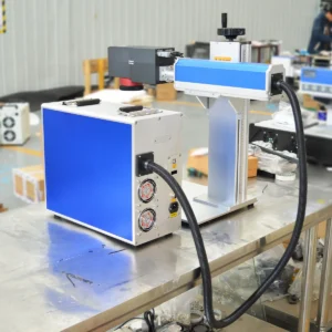
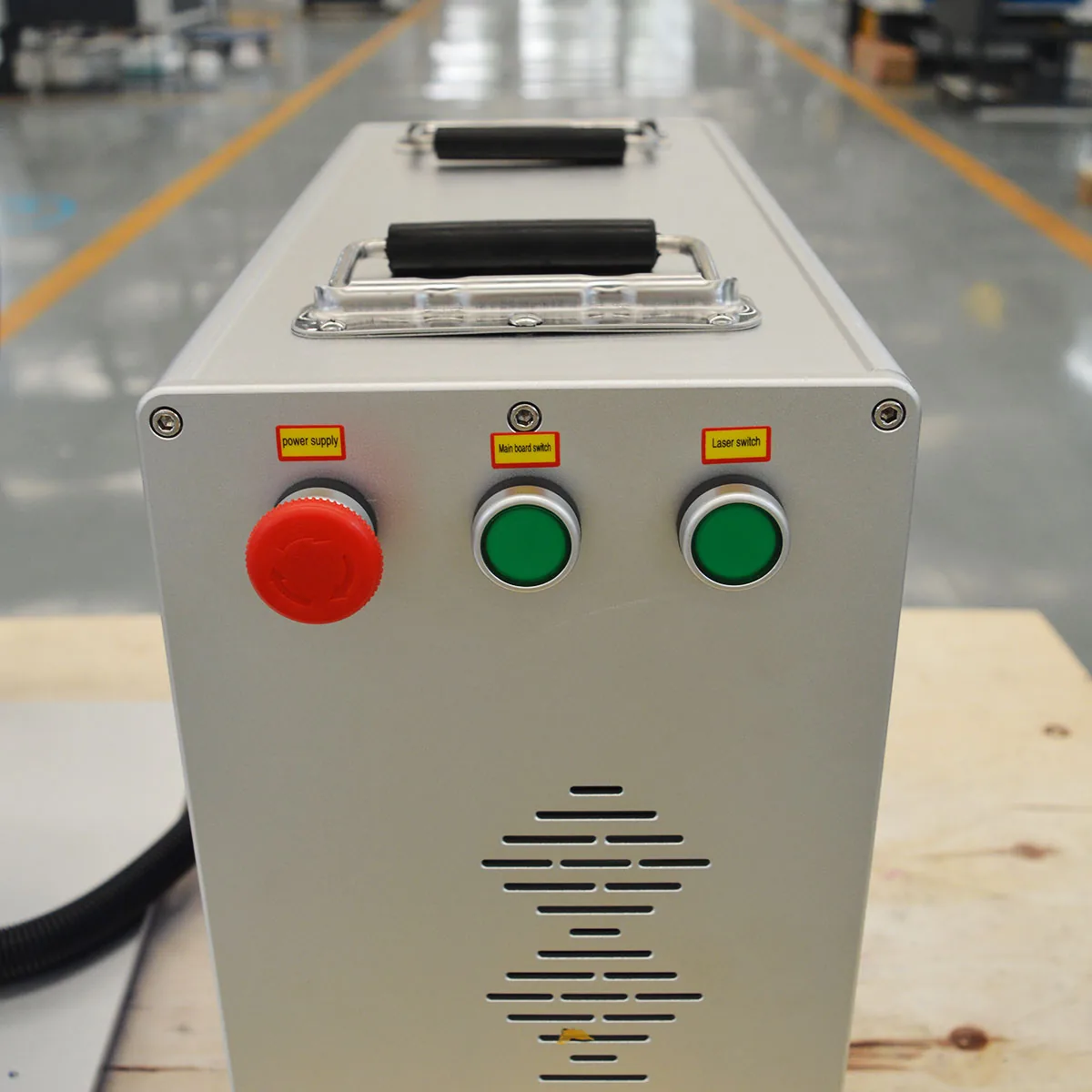
Laser marking is most valuable when identification has to stay with the part, change digitally from one part to the next, remain readable in a small area, or avoid mechanical contact with the workpiece. Those advantages are real, but they only matter if the actual material, surface, geometry and production process can support a stable marking window.
That distinction is what separates a useful laser-marking decision from a generic list of benefits. A laser may produce an excellent mark on one sample and still be the wrong production choice if the same result cannot be repeated across normal material variation, if the part cannot stay in focus, if the cycle becomes too slow after loading and verification are included, or if the required mark would be easier to achieve with a label, ink process or mechanical method.
This guide therefore looks at laser marking as a production decision rather than a technology claim: what it does especially well, where the limitations come from, which variables actually change the result, when another process may be more practical, and how a real sample test should influence the final machine configuration.
Why Manufacturers Choose Laser Marking in the First Place
The strongest reason to choose laser marking is not simply that it is fast or modern. Its real advantage is that it can combine direct-part identification, digital data control and non-contact processing in one repeatable operation. That combination is difficult to replace when a product needs a serial number, batch code, Data Matrix code, logo or other identifier that should remain on the workpiece while the content changes from part to part.
Direct identification can remove the weak link between the mark and the part
Ink and labels add information to a surface. Laser marking usually changes the workpiece surface itself through a mechanism such as color change, annealing, ablation, foaming or engraving. That difference matters when the identification needs to remain associated with the part during handling, assembly, cleaning or service.
It does not mean every laser mark has the same durability. A deep engraved metal mark, an annealed stainless-steel mark and a color-change mark on plastic are physically different results. Their resistance to abrasion, chemicals, repeated cleaning or outdoor exposure can also be different. “Permanent” is therefore not a universal laser property; it is an acceptance requirement that has to be proven for the material and service environment.
Digital content is where laser marking becomes especially powerful
A laser can change serial numbers, batch information, dates, QR codes and other variable content without replacing a stencil, character set or printing plate. That makes the process particularly attractive for traceability, short production runs with frequent data changes, and products that carry unique information.
The same software-controlled workflow can also connect with sensors, triggers, encoders, fixtures, vision positioning and production data. The important boundary is that a laser marker is not automatically a complete automated line. The digital marking process may be ready for integration while part presentation, PLC communication, verification, reject logic and safety control still require separate engineering.
Fine marks and machine-readable codes can fit where labels cannot
Laser marking can place relatively fine text, graphics and machine-readable codes into a limited marking area, which is useful on compact industrial parts where a large label is impractical. But the programmed graphic is only one part of the result. Spot size, marking field, focus, part height, surface response and code-quality requirements all determine whether the physical mark remains sharp and readable.

Non-contact marking removes one process variable, not all of them
Because the laser does not need a stylus, cutter or print head to press against the workpiece, there is no marking-tool contact force and no cutting edge wearing against each part. This can be valuable for small parts, delicate surfaces and production where physical contact would add another source of variation.
However, non-contact should never be interpreted as non-invasive. The material still absorbs laser energy. If the wavelength or process settings are unsuitable, the result may include burning, melting, haze, swelling, discoloration or deformation. The advantage is freedom from mechanical contact, not freedom from material interaction.
Lower marking-consumable dependence can simplify repeated production
The marking process itself generally does not require ink cartridges, label stock or printing plates. In repeated production this can reduce routine consumable handling and remove issues such as ink drying, smearing or label adhesion from the marking step.
That advantage should not be oversold as “maintenance free.” Extraction filters, protective optics, fixtures, motion components, cooling and electrical systems still need appropriate attention. The practical benefit is lower dependence on marking consumables, not the absence of maintenance.
Where Those Advantages Break Down in Real Production
Most laser-marking disadvantages are not isolated weaknesses; they are signs that the process has moved outside a stable operating window. A material that absorbs the chosen wavelength poorly, a curved part that moves out of focus, a coating that varies from batch to batch, or a cycle dominated by handling can all turn an apparently strong laser application into an unstable or uneconomical one.
Material response sets the first boundary
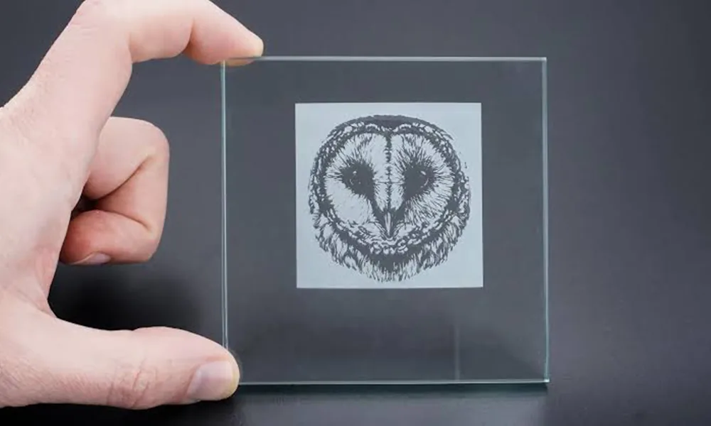
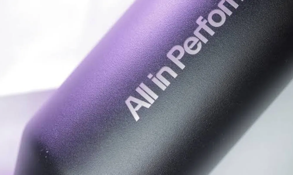
There is no single laser process that produces the best result on every material. Metals, plastics, coatings, glass, ceramics, wood and other substrates interact differently with different wavelengths and pulse conditions. Even parts sold under the same general material name can behave differently because of grade, additives, pigment, coating thickness or surface finish.
This is why “Can this material be laser marked?” is usually too broad a question. The useful question is whether the actual material can produce the required effect—dark contrast, light contrast, coating removal, surface color change, engraving depth or code readability—without unacceptable secondary damage.
Focus and geometry can matter more than the laser source
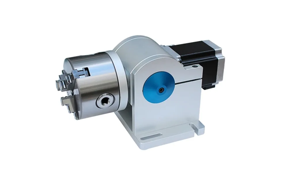
A flat plate held at a fixed height is an easy optical problem. A cylindrical connector body, stepped casting or recessed surface is different because portions of the target can move away from the intended focal plane or become difficult to access. The scanner can follow the programmed path perfectly while the physical mark loses sharpness or contrast because the workpiece is no longer presented consistently.
That is why curved or height-variable parts sometimes require a rotary axis, dynamic focusing, 3D marking or a custom fixture. The part is not necessarily “unmarkable”; the engineering problem has simply shifted from laser power to how the surface is presented to the beam.
Scanner speed is not production throughput
Laser scanning can be fast, but the complete production cycle may include loading the part, locating it, confirming focus, retrieving variable data, marking, checking the result and unloading the workpiece. Mark size, content complexity, depth and target contrast can also change the actual exposure time.
For production planning, the meaningful question is therefore not “How fast can the galvo scan?” but “How many acceptable parts can the complete process produce per hour?” A fast laser process can still be a slow workstation if part presentation and verification dominate the cycle.
Repeatability belongs to the process window, not just the machine
A machine can repeat the same programmed path while the final mark changes because the material formulation, coating thickness, surface finish, part height or fixture location has changed. Production repeatability only appears when the important inputs are stable enough for the selected parameters to keep producing the same acceptable result.
This is one of the most important engineering boundaries in laser marking. The machine is responsible for repeating its motion and energy delivery; the production process is responsible for keeping the material and workpiece presentation inside the range where that repetition still creates the required mark.
Cost, safety and deep marking can change the process choice completely
Laser marking usually requires more initial equipment investment than labels, simple manual marking or some printing methods. That cost can make sense when the application benefits from permanent direct identification, frequent variable data or repeated production, but it may be difficult to justify for a very small number of temporary marks.
Safety and fume control also belong to the complete system. Enclosures, interlocks, reflective workpieces, maintenance access and operator interaction can all affect the final safety design; an enclosed machine should not automatically be treated as a final Class 1 system without evaluating the complete accessible-emission and safety design. Laser-material interaction can also create particles, vapors or fumes that have to be evaluated for the actual material and process. Likewise, very deep material removal may be technically possible but too slow to be the most practical option. A process designed specifically for deep mechanical identification can sometimes be a better fit.
What Actually Determines the Laser Route and Marking Result?
Buyers often begin with a laser name—Fiber, UV or CO₂—but the application should begin with the result. The material family narrows the likely direction, yet the required contrast, depth, surface appearance, thermal sensitivity, marking field and production geometry decide whether that direction remains suitable.
Fiber, UV and CO₂ are starting routes, not universal material recipes
Fiber lasers are commonly considered for metals and many industrial direct-part marking tasks. UV lasers are often evaluated when a material or surface benefits from a different wavelength and lower thermal loading. CO₂ lasers are commonly considered for many organic materials and some non-metal substrates. Those descriptions are useful for first-pass routing, but none of them replaces a real application test.
| Laser route | Where it often enters the discussion | What still has to be validated |
|---|---|---|
| Fiber | Metals, industrial components, direct marking and engraving tasks | Alloy, surface finish, coating, target contrast or depth, marking field and cycle time |
| UV | Plastics, electronics, coated or appearance-sensitive parts where thermal response needs closer control | Polymer formulation, additives, surface response, cosmetic effect and acceptable heat impact |
| CO₂ | Wood, leather, paper and many other organic or non-metal materials | Material composition, surface effect, contrast, burning or charring risk and required production speed |
The useful engineering rule is simple: choose the route that can create the required marking mechanism on the real surface, then confirm it under the actual geometry and production constraints. Do not select a machine only because a general material chart places the workpiece in one category.
Working area and detail have to be evaluated together
A larger marking field can be convenient for large workpieces, but it should not automatically be treated as an upgrade. Optical configuration, spot size, focal behavior and required detail all interact with the chosen field. If the application needs a compact Data Matrix code or fine characters, the usable field should be large enough for the part without sacrificing the mark quality the application actually requires.
The target mark is a better specification than “clear marking”
“Clear” is too subjective to drive a technical decision. A useful requirement defines whether the target is dark contrast, light contrast, color change, coating removal, engraving depth, visual appearance, human readability, scanner readability or a combination of these. It should also state whether abrasion, chemical exposure, repeated cleaning or other durability conditions matter.
That level of definition changes machine selection. A setup optimized for maximum darkness may not be appropriate for an appearance-critical coated surface. A deeper mark may add cycle time without improving the actual acceptance requirement. The result has to be specified before the machine can be judged correctly.
Where Laser Marking Is Genuinely a Strong Fit
Laser marking is at its strongest when several needs appear together: the mark should stay directly on the part, data may change frequently, available space is limited, the product can be positioned consistently and the required result can be validated without damaging the surface. In these cases the laser is solving a real production problem rather than simply replacing another marking method.
Traceability on finished industrial parts
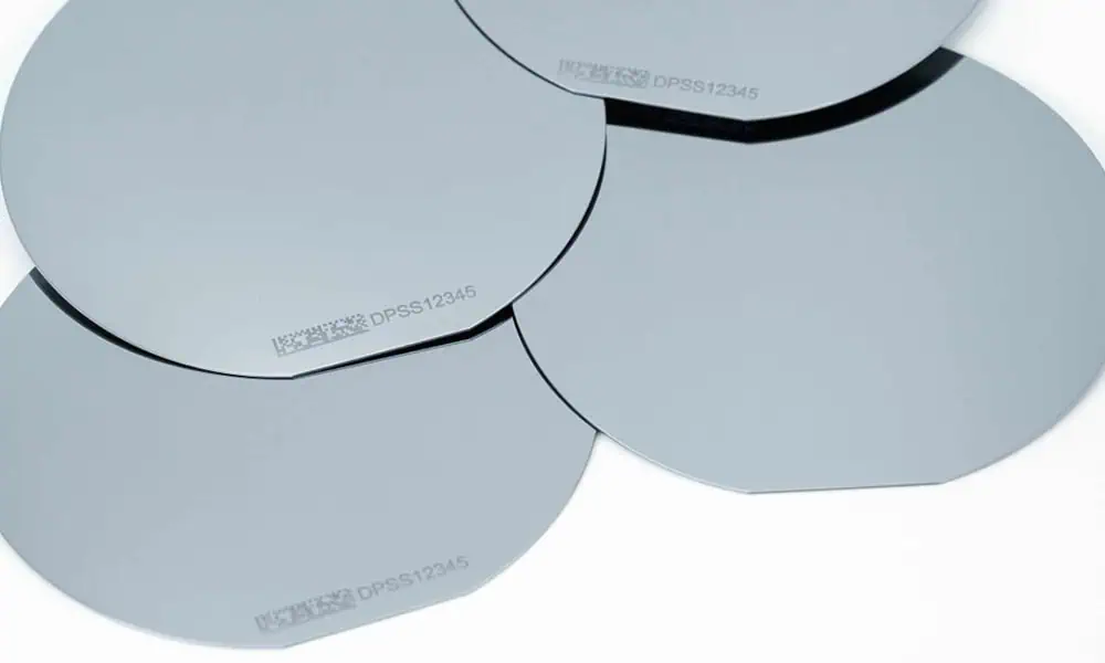
Serial numbers, part numbers, batch codes and machine-readable identifiers are a natural fit when the information needs to remain with the component rather than on separate packaging. The value increases when the part moves through several downstream operations, because the identification is physically tied to the product instead of depending on a removable label.
Small components with dense information
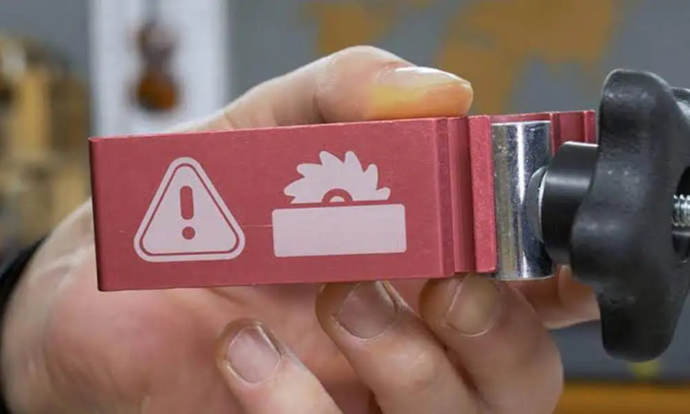
When a small surface has to carry text, a serial number and a compact 2D code, laser marking can provide a practical way to place information without adding a large label. The limitation is that code quality still depends on the real spot size, contrast and focus stability. A compact code is only useful if it remains readable by the intended scanner.
Products with frequent variable coding
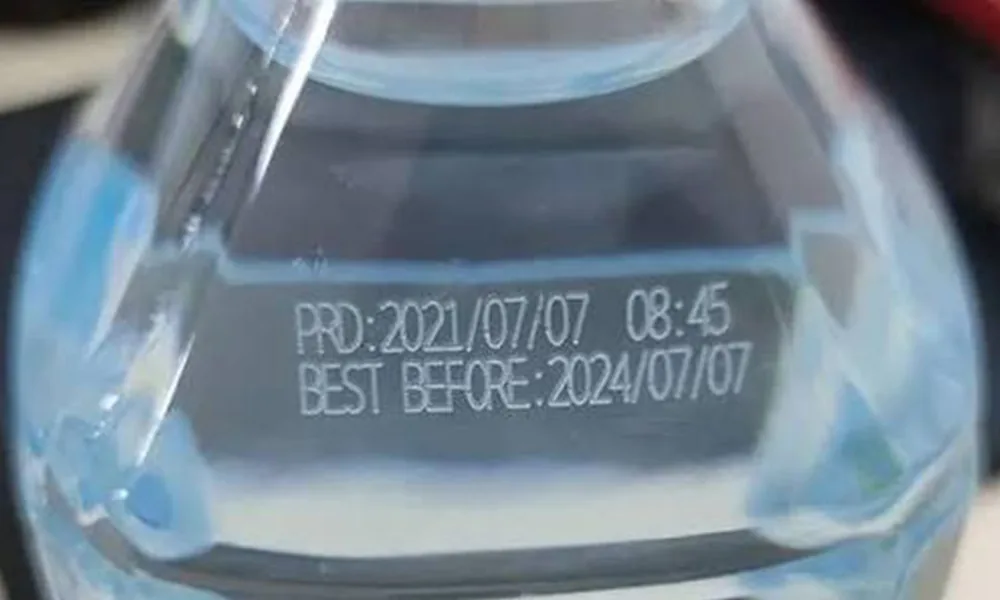
Date information, batch codes, serial numbers and other production data can change without physical tooling changes. That flexibility is especially valuable when information changes frequently or each product needs unique content. The production system still has to control where the data comes from, how the correct record reaches the laser and how the finished mark is verified.
Applications where the process can be controlled repeatably
The best laser-marking projects are not necessarily the most technically complicated. They are the ones where the workpiece can be presented consistently, the focal condition can be maintained, the material variation is understood, the acceptance criteria are clear and the required safety and extraction measures can be integrated into the workstation.
In other words, controllability is itself a best-fit signal. A technically markable part with uncontrolled geometry or undefined acceptance criteria may be a weaker project than a simpler part with a well-understood material, fixture and production requirement.
When Another Marking Method May Be More Practical
Laser marking is not automatically better than printing, labels or mechanical marking. It is better only when its specific strengths matter enough to justify the equipment and process control. If the identification is temporary, replaceable, extremely deep, very low-volume or difficult to process safely, another method may solve the real requirement with less complexity.
| Method | Where it can be attractive | Where the trade-off appears |
|---|---|---|
| Laser marking | Durable direct identification, variable data, fine codes, non-contact processing | Higher initial investment, material/process validation, geometry and safety requirements |
| Ink printing | Simple coding, low initial equipment cost, temporary or frequently changed marks | Consumables, drying or smearing, adhesion and long-term durability |
| Labels | Simple implementation, replaceable information, easy visual differentiation | Adhesion, environmental resistance and the fact that the identification is not physically part of the component |
| Mechanical engraving or impact marking | Deep physical identification where depth is the main requirement | Tool contact, wear, force on the workpiece and less flexibility for dense changing data |
A useful decision test is to remove the word “laser” from the requirement and describe only what the mark must do. If the real need is temporary pricing information, a permanent direct mark may add no value. If the main need is very deep identification on a robust component, a mechanical method may deserve comparison. If the part needs serialized traceability, fine codes and frequent digital changeovers, laser marking becomes much harder to replace.
How to Validate Laser Marking Before Choosing a Machine
Once laser marking looks suitable in principle, the next step should be a controlled sample test rather than an immediate machine purchase. A catalogue specification can describe laser power, working area and equipment structure, but it cannot prove that the actual material, coating, geometry and target mark will remain acceptable in production.
Start with the real workpiece, not a generic substitute
Material grade, polymer formulation, pigment, coating, thickness and surface finish can all change the response. If production parts vary between batches, validation should include that variation instead of proving the process only on one visually convenient sample. Otherwise the test may remove the very uncertainty that later causes instability.
Define acceptance before adjusting parameters
The sample test should begin with a measurable or at least clearly observable target: required contrast, engraving depth, visual appearance, code readability, surrounding surface condition and any durability requirement that actually matters. This prevents the test from optimizing the wrong characteristic. A darker mark is not automatically better if it damages the cosmetic surface; a deeper mark is not automatically better if it adds cycle time without improving the real requirement.
Change variables deliberately and record what changed
When several parameters are changed at once, it becomes difficult to understand why one sample improved and another failed. A useful application test changes the important variables in a controlled way while recording the workpiece condition and result. The purpose is not to collect as many parameter combinations as possible; it is to identify a practical process window that remains stable across the variation the production line is expected to see.
Test the complete production cycle, not only the laser exposure
Repeat the result across multiple parts and measure the process that will actually exist in production: loading, locating, data retrieval, marking, verification and unloading. If a fixture is required, use it. If a code must be scanned, verify the code. If the part position changes, include that variation in the test. One attractive sample proves that a mark can be created; it does not prove that the production process is ready.

Useful information for an application review includes the material and surface condition, part dimensions, marking area, required content, target result, production rate and clear workpiece photos or drawings. Those inputs make it possible to test the application rather than force the application into a machine selected too early.
How the Sample Result Should Determine the Final Machine Configuration
The machine should be the physical implementation of a proven process, not the starting assumption. Once the real workpiece has been tested, the result should indicate which laser route can achieve the target mark, how large the working field needs to be, whether the surface stays inside an acceptable focal range, and whether part positioning can be controlled with a simple fixture or needs rotary, vision, 3D focusing or another positioning method.
The same test should inform the workstation around the laser. Production volume influences whether loading remains manual or requires automation. Material and process behavior influence whether fume extraction is needed. Operator access and the actual optical configuration influence enclosure and safety design. Variable data and quality requirements influence whether the machine needs code generation, external data input or verification functions.
This sequence matters because it prevents a common purchasing mistake: choosing a machine by headline power, working area or price and then trying to make the application fit afterward. A better sequence is workpiece → required mark → sample result → process window → production cycle → machine configuration.
If you are ready to compare equipment after those requirements are defined, you can review the laser marking machine options with the actual material, target result and cycle requirements in mind.
Laser Marking Advantages and Limitations: FAQs
Is laser marking permanent?
Laser marking is commonly used for permanent or highly durable identification because the process changes the workpiece surface rather than applying a separate label or ink layer. Actual durability still depends on the material, marking mechanism and service environment.
Does laser marking damage the material?
Not necessarily. A correctly selected and tuned process can create the required mark with an acceptable surface effect. An unsuitable wavelength or process window can cause unwanted heating, burning, melting, discoloration or deformation, so the real material should be tested.
Can laser marking be used on every material?
No single laser process is best for every material. Different wavelengths and process conditions interact differently with metals, plastics, coatings, glass, wood and other substrates. The required marking result should be evaluated together with the actual material and surface.
Does laser marking require consumables?
The marking process generally does not require ink cartridges or label stock, but the complete machine is not maintenance-free. Extraction filters, optics cleaning, fixtures and other machine components may still require routine maintenance or replacement.
Is laser marking expensive?
The initial equipment cost is normally higher than many simple temporary marking methods. Whether it is economical depends on production volume, traceability needs, required durability, variable data, consumable use and the complete production process.
How do I know whether my part is suitable for laser marking?
Start with the actual material, surface, geometry and required result. If the process direction appears suitable, test the real workpiece and evaluate contrast, readability, surface effect, repeatability and practical cycle time before finalizing the machine configuration.