
Packaging & Coding Applications
Laser Marking & Coding for Packaging
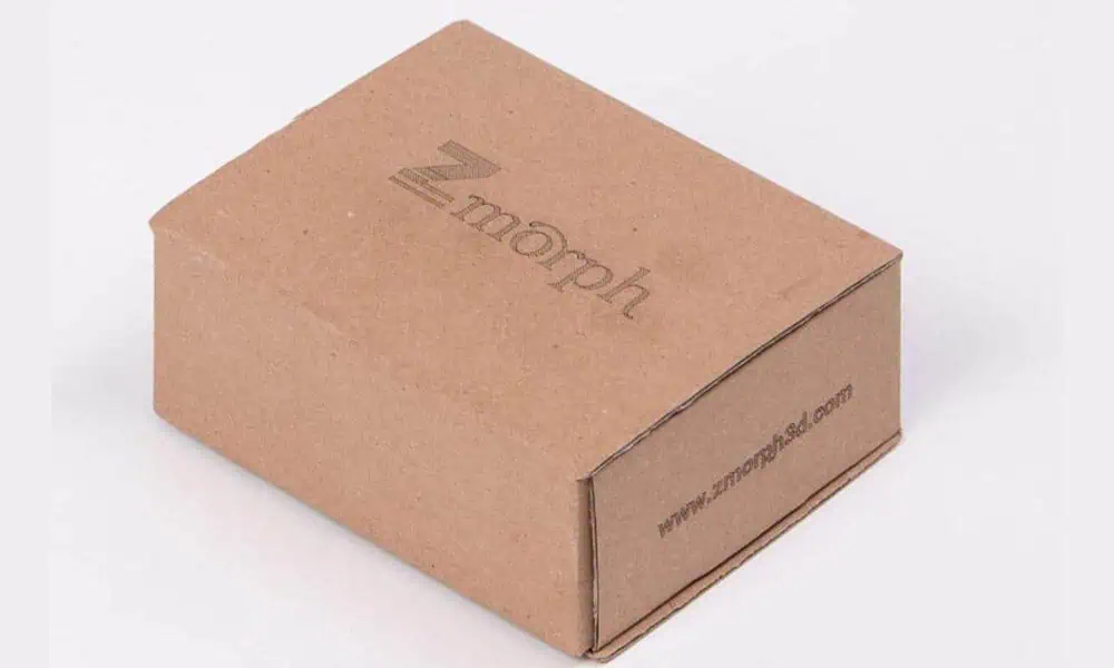
Laser coding is worth evaluating when cartons, labels, films, pouches, bottles, containers, caps, closures, or other finished packages need repeatable date, batch, lot, expiry, identification, barcode, 2D-code, or simple graphic marking.
Do not choose the machine from the package name alone. Start with the real finished package, code content, surface construction, target result, geometry, data flow, production method, and acceptance criteria. These inputs determine the first laser route to test, what must be validated, and how the final machine should be configured.
Which Packaging Formats Should Be Evaluated?
Packaging format defines the handling problem; the finished material and surface construction determine whether a laser process is technically suitable. A carton, bottle, cap, label, or pouch is not a laser recipe. The same package format can use different substrates, pigments, coatings, laminates, inks, varnishes, or barrier layers that respond differently to the same wavelength.
| Packaging format | Typical marking considerations | What to confirm before testing |
|---|---|---|
| Cartons, paperboard & corrugate | Flat or folded panels, printed surfaces, coatings, contrast, code density, moving-line presentation | Board construction, print/coating layer, code area, line speed, allowable discoloration or ablation |
| Labels & coated labels | Top-layer response, liner or adhesive effects, fine text, barcodes, 2D codes, web handling | Face stock, coating/ink, adhesive construction, code size, inspection method, stationary or moving web |
| Films, pouches & sachets | Thin walls, laminates, barrier layers, heat sensitivity, distortion, puncture risk, moving material | Layer stack, thickness, seal/barrier requirements, allowable surface change, line presentation |
| Plastic bottles & rigid containers | Polymer formulation, pigment, wall thickness, curvature, focus, orientation, part movement | Actual resin/color, coating or label, mark zone, curvature, support method, inspection requirement |
| Caps & closures | Small curved surfaces, molded texture, pigment, repeated orientation, high part rate | Material/color, top or side marking area, orientation repeatability, fixture or line presentation |
| Metal or glass packaging surfaces | Bare or coated metal response, lacquer/paint layers, glass surface integrity, curved presentation | Whether the target is the substrate or top layer, required visual result, allowable surface effect, handling method |

Packaging Application Routes by Industry
Industry routing comes after the package format and process conditions are understood. Food, beverage, cosmetics, and pharmaceutical projects can use similar package formats but have different code, inspection, appearance, validation, and production-control requirements.
Food Packaging
Evaluate the finished package construction, date/batch content, allowable surface change, inspection requirement, and actual line cycle for the specific food-packaging format.
Beverage Bottles & Caps
Curved surfaces, cap orientation, container color, package movement, and mark position can change the handling and focus problem as much as the laser source itself.
Cosmetics Packaging
Appearance-sensitive packs require the code to be judged together with coating, finish, brand-facing surface quality, variable data, and acceptable visible change.
Pharmaceutical Packaging
Start from the required identification content, package construction, inspection method, production controls, and project-specific validation or regulatory requirements before selecting the marking process.
Why Are Packages Marked or Coded?
The marking requirement should be clear before deciding whether laser is the right process. Packaging is commonly coded so production, distribution, inspection, or the end user can identify what the package is, when or where it was produced, and how it should be tracked or verified.
What Is Usually Marked on Packaging?
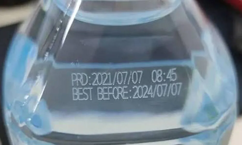
Typical package coding content includes manufacturing or expiry dates, batch and lot numbers, shift or line identifiers, serial or product-variant data, text, logos, barcodes, and 2D codes. Some fields stay fixed for a product while others change by batch, time, line, or individual item, so the application review should define both the visible content and the variable-data workflow.
Production and traceability information
Date, batch, lot, shift, line, serial, product variant, or other variable data can connect a physical package to the correct production record and help distinguish one run from another.
Shelf-life and use information
Expiry, best-before, manufacturing date, or similar information may need to remain legible through the package’s intended handling and storage conditions. The exact requirement is project- and market-specific.
Human- and machine-readable identification
Text, logos, barcodes, and 2D codes may be used for identification, scanning, verification, inventory, serialization, or other production workflows. A visibly dark mark is not automatically a machine-readable mark.
Why evaluate laser after the need is defined?
A laser route is worth testing when the project benefits from non-contact digital marking, variable data, a consumable-free marking mechanism at the point of coding, or direct integration with a stationary or moving production process. These advantages matter only if the real package passes the required quality and cycle tests.
What Determines the Laser Coding Result?
Laser coding results are controlled by more than the package material name. The useful test input is the combination of code, finished surface, desired mark mechanism, geometry, presentation, inspection method, and production cycle.
| Variable | What to provide | Why it changes the result |
|---|---|---|
| Code content | Date, batch, lot, expiry, text, logo, barcode, 2D code, fixed fields, and variable fields | Character density, filled areas, module size, and data changes affect marking time, edge definition, software workflow, and inspection. |
| Mark size & available area | Overall dimensions, smallest meaningful feature, available marking zone, and required orientation | Field size, focal condition, positioning tolerance, and the amount of laser work per package depend on the real code geometry. |
| Finished package construction | Base substrate, pigment, color, coating, ink, varnish, laminate, adhesive, metallized layer, or protective finish where known | The laser interacts with the layer that actually receives the beam. A similar base material can mark differently after printing, coating, lamination, or formulation changes. |
| Target mark mechanism | Color change, surface ablation/removal, engraving/etching, foaming, or another acceptable visible effect | Different wavelengths and pulse conditions may create different mechanisms, contrast, residue, and thermal load. |
| Package limits | Allowed discoloration, melting, distortion, coating loss, residue, puncture, barrier damage, or adjacent-surface effect | The usable process window is bounded by both code quality and package integrity. |
| Geometry & presentation | Flat or curved surface, wall thickness, orientation, fixture, indexed position, web motion, conveyor motion, or free presentation | Geometry affects focus and field use; presentation affects position repeatability, trigger timing, and whether motion must be synchronized. |
| Inspection & verification | Human reading, barcode/2D reader, vision check, required pass/fail method, and reject logic | The acceptance method determines what contrast, edge quality, position, and data correctness must actually be achieved. |
| Production target | Batch size, changeovers, loading method, line speed, target accepted-part cycle, and expected yield | The system must satisfy the complete production cycle, not only nominal scan speed or laser-on time. |
Variable Data Is Part of the Process, Not Only the Artwork
Confirm which fields are fixed and which change by product, batch, date, shift, serial number, or upstream production input. Variable data changes job selection, trigger logic, verification, changeover, and error-control requirements as well as the mark itself.
What Packaging Marking Result Should You Target?
Mark quality is an acceptance problem, not a single laser setting. The process must create the required information while keeping the package within the agreed surface and functional limits.
Contrast and Legibility
Judge contrast at the viewing or inspection condition that matters in production. Fine text, small features, and dense codes should be evaluated at their real size rather than inferred from a larger demonstration mark.
Package Integrity and Surface Appearance
A high-contrast code is not acceptable if the same setting deforms a thin wall, damages a barrier or coating, creates objectionable residue, punctures a film, or produces another surface change outside the agreed limits.
Machine-Readable Codes When Required
If the package uses a barcode or 2D code, validate it with the user’s actual inspection method and representative production samples. Visible appearance alone should not be treated as proof of verified code quality.
Which Laser Route Should Be Tested First?
The first-test route should come from the finished surface and desired mark mechanism, not from the package name alone. The table below is a screening guide for sample trials, not a guarantee that one wavelength will work across every formulation, coating, color, laminate, or production line.
| Package / surface condition | Practical first route to evaluate | Why start there | What can change the route |
|---|---|---|---|
| Paperboard, cartons, corrugate, or laser-responsive printed/coated paper | CO₂ is often a practical first test; UV is worth comparing when fine contrast or lower thermal loading is important. | Paper and many organic/coated packaging surfaces can respond well to longer-wave infrared processing, while UV can create a different high-contrast surface response on some papers and coatings. | Ink/coating chemistry, board color, desired ablation depth, fine-code requirement, line speed, residue, and allowable discoloration. |
| Thin flexible films, pouches, sachets, or heat-sensitive label constructions | UV is often the first route to screen when minimizing thermal deformation or puncture risk is a priority; CO₂ remains relevant when the film or top layer is designed to respond to it. | Thin multilayer packaging can have a narrow thermal window, so the test must balance code contrast against distortion, barrier damage, or pinholes. | Film chemistry, thickness, laminate stack, metallized layers, target mechanism, seal/barrier requirements, and moving-web speed. |
| Plastic bottles, rigid containers, or plastic caps | UV is a useful first comparison for heat-sensitive or fine high-contrast marks; CO₂ or 1064-nm fiber/MOPA may be better on formulations, pigments, additives, or coatings that respond to those wavelengths. | Plastic response varies strongly with resin formulation, pigment, additives, wall thickness, and surface finish. | Actual resin/color, transparency, marking additives, wall thickness, coating, desired contrast, curvature, and acceptable heat effect. |
| Bare metal caps, cans, foils, or metallic package components | Fiber/MOPA is normally the first route to evaluate on the exposed metal surface. | Near-infrared fiber systems are commonly used for direct metal marking and can support different surface-marking mechanisms depending on the alloy and finish. | Metal alloy, anodizing, lacquer, paint, protective coating, desired color/depth, and whether the target is the metal or only the top layer. |
| Painted, lacquered, printed, laminated, or metallized surfaces | Test the top layer as its own process problem. CO₂, UV, or fiber/MOPA may be the correct first route depending on which layer should change and which layer must remain protected. | The beam interacts with the exposed layer first; the base substrate alone does not predict the mark. | Layer thickness, absorption, color, bond to the substrate, removal depth, residue, and the amount of underlying-layer exposure allowed. |
| Glass bottles or containers | CO₂ or UV can be screened depending on the desired surface mark and damage tolerance. | Glass marking is constrained by surface stress, local thermal effect, crack/chip risk, mark texture, and code-detail requirements. | Glass composition, wall thickness, coating, curvature, required contrast/texture, and allowable micro-damage. |
Common Failure Modes and What to Check First
When a trial fails, the next step should be diagnosis rather than automatically increasing power. Record the symptom, separate material/surface effects from focus, geometry, motion, and data-flow problems, and change one variable group at a time.
| Observed failure | Check first | Evidence to collect | Next test direction |
|---|---|---|---|
| Weak or inconsistent contrast | Package batch, surface coating/ink, color, focus, contamination, and whether the chosen wavelength is creating the intended mark mechanism | Unmarked and marked samples from multiple packages/batches, surface description, identical code geometry, and recorded test settings | Run a controlled parameter matrix; if the acceptable window remains narrow, compare another wavelength or mark mechanism instead of only adding energy. |
| Film distortion, pinholes, melted edges, or thin-wall deformation | Thermal input, dwell/overlap, focus, unsupported package wall, and material thickness | Front/back surface inspection, deformation around the code, film thickness, support method, and samples across the intended speed range | Reduce local thermal load, change scan strategy or speed, improve support, and compare a lower-thermal-impact route such as UV where the material response supports it. |
| Coating damage or substrate exposure beyond the intended mark | Top-layer thickness/variation, removal mechanism, pulse/energy condition, and underlying substrate response | Good and failed samples, coating information where known, edge quality, residue, and whether the base layer has been attacked | Narrow the removal window, reduce process aggressiveness, or test a wavelength that couples more selectively to the target layer. |
| Barcode or 2D code looks visible but reads poorly | Smallest module/feature, edge definition, contrast uniformity, geometric distortion, marking position, and verifier/reader setup | Actual reader/verifier result, failed code image, real code size, package curvature, and repeat results across multiple samples | Correct code geometry and positioning first, then optimize the mark process. Do not judge success from visual darkness alone. |
| Mark position drifts between packages | Part presentation, fixture/stop repeatability, sensor or trigger timing, conveyor motion, encoder/synchronization, and focus variation | Position-error pattern, package orientation, trigger signal timing, line speed, and repeated marked samples | Stabilize presentation or triggering; add sensing, vision, or synchronized motion only when the measured variation justifies it. |
| Static sample passes but line result fails | Production speed, motion synchronization, dwell time, changing focus, package vibration, data update timing, and inspection timing | Static vs. moving samples, complete cycle timing, line-speed range, trigger/data logs where available, and accepted/rejected samples | Re-test under real line conditions and size the marking field, data flow, trigger method, and motion architecture around the accepted moving result. |
| Correct mark quality but wrong variable data | Job selection, upstream data source, trigger logic, field mapping, changeover control, and verification logic | Expected vs. actual code content, event timing, job/recipe record, and inspection result | Validate the data path independently from laser parameters before increasing production speed. |
How Does Laser Coding Fit Into the Production Workflow?
The useful production number is accepted-part throughput. It includes changeover, package presentation, positioning, variable-data loading, triggering, marking, verification, reject handling, downstream transfer, and extraction or ventilation where the tested process requires it.
| Workflow step | Questions to test |
|---|---|
| Setup & changeover | How are product, code, recipe, marking area, and acceptance criteria changed between runs, and how are wrong-job errors prevented? |
| Package presentation | Is the package manually loaded, fixtured, indexed, web-fed, or moving continuously? Which orientation and focus variation must the process tolerate? |
| Variable data & trigger | Where does the code data come from, when is it updated, what event triggers the mark, and what prevents one package from receiving the wrong record? |
| Mark execution | How do code area, density, content changes, passes, field use, focus, and motion change laser-on time and process stability? |
| Verification | Does the project need operator inspection, barcode/2D reading, vision confirmation, position checking, or another pass/fail method? |
| Reject / rework / record | What happens to a failed package, how is it separated from good product, and what production or quality data must be retained? |
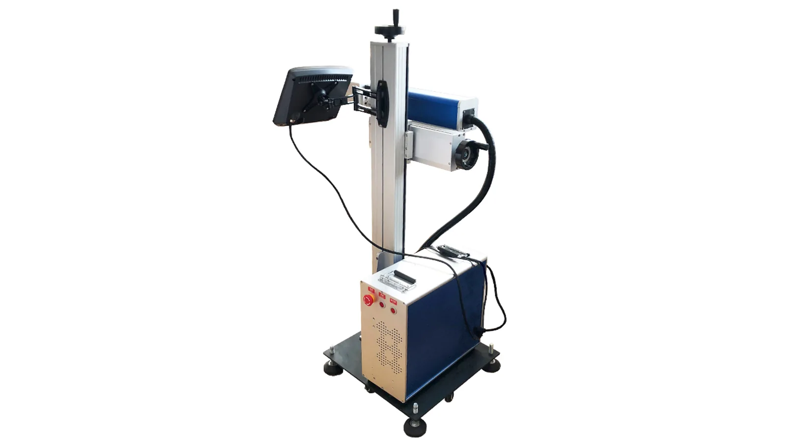
A higher nominal scan speed does not guarantee more accepted packages per hour. Compare complete tested cycles at the same quality, data, positioning, and inspection standard.
What Should Count as a Passed Packaging Sample Test?
Test the real finished package, not only a generic material swatch or one best-case demonstration. Include representative variation in color, coating, finish, thickness, geometry, supplier batch, and package presentation wherever those factors can change the result.
| Acceptance area | Pass when | What to record |
|---|---|---|
| Mark quality | The agreed contrast, legibility, character definition, code definition, and visual consistency are achieved at the real mark size. | Representative marked samples, code dimensions, viewing condition, and test settings. |
| Data correctness | The required fixed and variable fields match the intended production data for each test package. | Expected/actual data, job/recipe identification, trigger condition, and sample sequence. |
| Package integrity | Melting, distortion, puncture, coating damage, residue, discoloration, or adjacent-surface effects remain within the agreed limits. | Good/failed samples, front/back inspection where relevant, and any functional packaging checks required by the project. |
| Code verification | Barcodes or 2D codes pass the user’s actual inspection or verification method where machine readability is required. | Reader/verifier result, code size, position, and representative samples across the expected variation. |
| Position repeatability | The mark stays inside the approved zone and remains in an acceptable focus condition across representative packages and presentation variation. | Position measurements or visual reference, orientation, fixture/line condition, and repeated samples. |
| Production result | The complete loading/presentation → data/trigger → mark → verify → accept/reject cycle meets the required accepted-part rate. | Full-cycle timing, line-speed condition, inspection time, rejects/rework, and accepted yield. |
| Repeatability | Multiple representative packages and, where relevant, more than one normal production batch pass the same acceptance logic. | Sample count, package/batch identity, pass/fail result, and the usable process window rather than one best-looking setting. |
How Do Sample-Test Results Determine the Final Machine Configuration?
The sample test should answer configuration questions, not merely prove that one package can be marked. Each accepted test result should be translated into a system requirement so the final machine reflects the proven process window and production method.
| What the test proves | What it determines in the final configuration |
|---|---|
| Which wavelength and process window produce the accepted mark without unacceptable package damage | Laser-source family and, where relevant, pulse/energy-control direction; the final operating range should stay inside the tested acceptance window. |
| Required code size, smallest feature, field coverage, and focus margin | Lens / marking-field choice, optical setup, working distance, and whether one field is sufficient or indexing/coordinated movement is required. |
| Package curvature, height variation, orientation, and support needs | Fixture, package stop, Z-height strategy, rotary or coordinated motion where appropriate, and whether vision-assisted positioning is justified. |
| Measured position variation on a stationary or moving line | Mechanical positioning, sensor/trigger arrangement, encoder or synchronization requirement, and the need for vision or motion compensation. |
| Variable-data source and correct-code verification | Software workflow, job/recipe handling, upstream data interface, trigger logic, inspection link, and error-proofing requirements. |
| Actual barcode/2D-code inspection result | Whether the system needs a reader or vision-verification station, how verification is triggered, and how failed packages are identified or rejected. |
| Fume, smoke, residue, or odor observed during the accepted marking process | Whether local extraction or ventilation is required and how it should be positioned without interfering with package presentation or marking. |
| Accepted complete cycle time and line-speed result | Manual workstation, indexed station, conveyor or synchronized moving-line architecture, handling capacity, and the level of automation required to meet accepted-part throughput. |
What to Send for a Packaging Application Review
A useful machine recommendation starts with enough information to reproduce the real packaging decision problem. You do not need to choose the laser in advance; provide the application inputs needed to run a meaningful sample test:
- the real finished package or representative production samples;
- package format, dimensions, geometry, orientation, and presentation method;
- material, pigment/color, coating, print, laminate, varnish, or supplier information where known;
- the required date, batch, lot, expiry, text, logo, barcode, 2D code, or other fixed/variable content;
- overall mark dimensions, available marking area, and smallest meaningful feature;
- target contrast, legibility, code inspection, position tolerance, and unacceptable package-change examples;
- variable-data source, trigger method, inspection method, and reject/rework requirement;
- target accepted-part cycle, line speed where applicable, batch size, and changeover expectations;
- handling, vision, extraction/ventilation, safety, line-interface, or automation constraints that are already known.
For project-specific handling, motion, synchronized line integration, or other non-standard automation, use the OEM & Custom Inquiry route. Standard application and quote paths remain in the final call to action.
Frequently Asked Questions
Can laser coding be used on every packaging material?
No universal compatibility claim is safe. The finished package, exposed layer, color, geometry, required mark, and allowable surface or functional change should be reviewed and tested before equipment selection.
What information can be laser coded on packaging?
Depending on the application, users may need dates, batch or lot information, expiry information, text, logos, barcodes, 2D codes, serial or other identification. The exact content, variable-data source, and smallest required feature should be included in the application brief.
Which laser should be tested first for packaging?
Start from the finished surface and desired mark mechanism. CO₂ is often screened first on paperboard and many organic/coated packaging surfaces; UV is often useful on heat-sensitive films and plastics; fiber/MOPA is commonly the first route on exposed metal and can also work on responsive plastics or coatings. The real package still has to confirm the route.
Is the fastest scan setting the best production setting?
No. The relevant measure is accepted-part throughput across the complete cycle, including package presentation, data loading, triggering, marking, verification, rejects, rework, and downstream handling.
How does the sample test affect the final machine configuration?
The test establishes the usable laser process, field and focus requirement, positioning method, data/trigger workflow, inspection need, extraction requirement where applicable, and the cycle time that the handling or automation architecture must support.
What should be sent for a packaging coding test?
Send representative finished packages, surface/material information where known, the real code content, mark dimensions, acceptance criteria, production mode, target cycle, and any positioning, data, inspection, or integration constraints.