Laser Marking Steel: Carbon, Mild, Tool & Alloy Steel
Carbon steel, mild steel, tool steel and alloy steel can all be laser marked, but the final result depends strongly on the real surface condition. Mill scale, oxide, rust, oil, black oxide, paint, coating, hardness and target depth can all change contrast, readability and repeatability.
Start with the steel family, then look at the actual surface
For many carbon steel, mild steel, tool steel and alloy steel parts, a fiber laser marking machine is the first route to evaluate. The harder question is whether the final surface can meet the required contrast, depth, readability and durability.
These names describe different, partly overlapping steel groups: mild steel is generally low-carbon steel, while many tool steels are also alloy steels. The material name alone does not set the laser recipe. A machined low-carbon part, a quenched-and-tempered alloy-steel component and a finished tool-steel insert can require different marking decisions because their final surfaces, permitted mark depth and downstream service differ. Check the steel grade and final manufacturing condition before using settings developed on another sample.
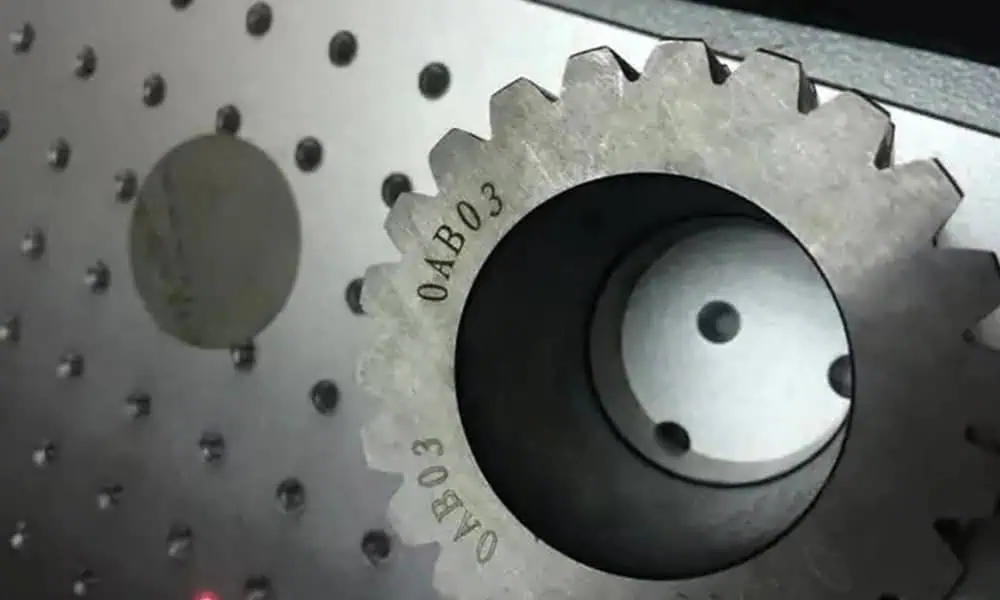
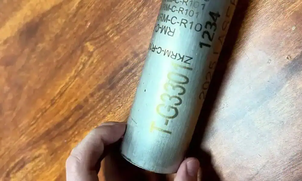
Tube geometry changes positioning and focus requirements
The steel marking process still depends on material and surface condition, but a cylindrical workpiece adds another layer of process control. Mark position, focus consistency and angular repeatability must stay stable on the real part.
How the steel surface changes the marking route
Separate the real surface condition before choosing parameters. The useful question is not just “can steel be marked?” but “what is on this steel surface, what process will the laser perform, and what must be verified afterward?”
Clean, machined carbon or mild steel
A clean machined face gives the laser a more consistent starting surface, but its finish still matters. Tool marks and roughness can break up fine lettering, while polished areas can create glare for a camera or handheld reader. Decide whether the requirement is visible identification, machine-readable contrast or actual engraved depth; a darker-looking mark does not automatically meet all three.
Mill scale, rust and uneven oxide
These layers vary in thickness and appearance across the same part. The first laser passes may change or remove the existing layer before producing a mark on the underlying steel, so a test on a cleaned coupon can be misleading. Compare the as-received part with an intentionally prepared area; if the results diverge, define a repeatable cleaning or marking sequence before finalizing parameters.
Machining oil and handling residue
Oil or coolant film can change local heating and create smoke or deposits that obscure a fine code. A mark that looks good on a freshly degreased demonstration piece may not repeat on parts from production. Set the cleaning and handling condition first, provide appropriate fume extraction, then evaluate the same marking process on representative production surfaces.
Heat-treated tool or alloy steel
For hardened tooling or heat-treated components, the issue is not simply whether the laser can leave a mark. It is whether the chosen depth, local thermal effect and edge condition are acceptable on the finished part. Where the marked area has a wear, sealing or fatigue-related function, review its allowable location and surface change before choosing deeper engraving. Validate on the final heat-treated and finished condition.
Separate coating removal from bare-steel marking
A mark on coated steel may come from changing or removing a surface layer, not from engraving the steel underneath. Removing a dark coating to expose a lighter substrate can create strong visual contrast while leaving little or no measured engraving depth in the metal.
The trade-off is protection: if the removed coating was part of the corrosion-control system, the exposed patch may need its own approval or follow-up treatment. Determine whether marking belongs before or after coating, then check the actual layer chemistry, removal boundary, residue, extraction requirements and final corrosion specification. Do not transfer a bare-steel process directly to painted, black-oxide or zinc-coated parts.
What steel parts are commonly marked?
Part geometry and the required mark type determine what needs to be verified beyond basic material compatibility.
Traceability on finished steel parts
For a serial number or Data Matrix on a machined carbon- or alloy-steel component, the first choice is the required reading method, not maximum engraving depth. Marking after the final surface finish avoids relying on a code that later machining or blasting may remove. If the code must survive wear or cleaning, test those conditions without placing an unnecessary deep groove on a functional surface.
Identification without damaging a working surface
A tool-steel insert may need a durable identifier, but deeper is not always safer. A recessed mark can create a burr or local notch and may be unsuitable on an active contact or highly stressed area. Agree on the permissible mark location and depth before developing the laser process; inspect edge condition as well as legibility on the finished hardened part.
Marking before or after blasting and coating
On a fabricated steel plate or painted housing, the process order can determine whether an identifier survives. A surface-color mark made before abrasive blasting may disappear; a code created by removing finished paint may expose bare steel. Choose the marking stage against the final finishing route, then check both readability and corrosion protection after all downstream steps.
Typical steel marking outcomes
Choose the result by inspection requirement, wear exposure and production time. Dark contrast, measurable depth, permanence and corrosion resistance are different acceptance questions.
The important distinction is what the laser changes. A dark surface mark mainly changes how the steel reflects light; shallow etching removes a small amount of material; deeper engraving removes more material over repeated passes; coating removal acts on a separate layer. A visually dark mark may be easy to see but wear away or lose scanner contrast, while a deeper mark can be more resistant to surface abrasion yet introduce rough edges, burrs and longer cycle times. Choose by the finished-part requirement rather than appearance alone.
| Target result | Typical process | What changes the result | What to verify |
|---|---|---|---|
| Dark surface mark | Controlled surface reaction or oxide-style contrast. | Grade, oil, scale, cleaning, heat treatment and roughness. | Visual contrast, scanner readability and post-cleaning appearance. |
| Surface etching | Light material removal for text, logos, scales or codes. | Focus, pulse settings, hardness and finish. | Edge quality, tactile feel, minimum feature size and code readability. |
| Deeper engraving | Repeated passes or higher-energy processing to create measurable depth. | Depth target, heat input, cycle time and part thickness. | Measured depth, burrs, edge texture, distortion and wear exposure. |
| Coating removal | Paint, powder coat, black oxide or another surface layer is removed or modified. | Coating chemistry, thickness, adhesion and fume behavior. | Clean edge, substrate exposure, residue, corrosion risk and extraction need. |
| Traceability code | Text, QR or Data Matrix must remain visually or machine readable. | Code size, glare, curved geometry and production repeatability. | Reader/scanner test on the final production part. |
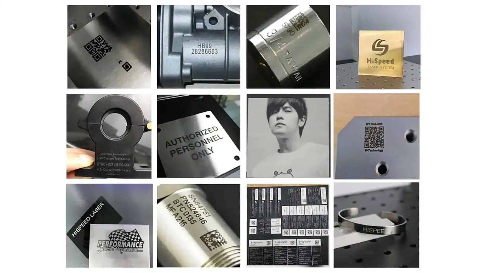
Which laser route is usually considered for steel?
For many steel marking tasks, a 1064 nm fiber laser is the first equipment family to evaluate. The final choice still depends on mark depth, line width, field size, fixture method, surface condition and cycle-time target.
A standard Q-switched fiber source is often enough for serial numbers, logos, etched identifiers and many readable codes on bare steel. MOPA fiber can be reviewed when pulse control, heat influence or contrast tuning matters.
Laser settings work together rather than independently. At a given average power, slower scanning increases the energy delivered along a line. Pulse frequency affects the spacing of successive pulses and, depending on the source, the energy in each pulse. Hatch spacing, focused spot size and repeat passes then change overlap and accumulated heating across a filled mark. Too little effective overlap can leave broken lines or uneven fills; excessive local energy can create melting, rough edges or a larger heat-affected region. A higher wattage label by itself does not determine which result will be cleaner.
The practical starting point is to fix the production surface and focus, select the required marking effect, then change a controlled group of parameters while checking contrast, edge quality, depth and cycle time. MOPA’s adjustable pulse duration can offer another control when an acceptable result is difficult with a fixed-pulse source, but it does not remove the need for steel-specific trials.
Why a good steel marking sample may fail in production
A clear mark on one cleaned sample does not prove that the same settings will work on every finished production part.
Consider a process approved on a clean machined coupon. If actual production parts arrive with coolant residue, mill scale or a different surface finish, the code may lose contrast even though the equipment and programmed settings have not changed. The relevant test is not a perfect demonstration sample; it is a representative set of parts in their normal marking condition.
The production sequence matters as much as the initial appearance. Abrasive cleaning may remove a shallow surface-color mark, later paint can cover a fine code, and removing a protective coating can create an exposed region that needs corrosion review. For a tube or an irregularly fixtured part, positioning variation can also move a fine code out of focus.
Approve the marking process against the actual acceptance requirement: readable code or visible text after the specified cleaning and finishing steps, measured depth if required, acceptable burr and edge condition, and cycle time on the real fixture. Record the material condition, marking settings and inspection method so a result can be reproduced rather than merely demonstrated once.
What to send before Zhuorui recommends a steel marking configuration
The final result should be confirmed on the real part when depth, dark contrast, code reading, coating removal, rust exposure or repeatability matters.
Material
- Steel type: carbon, mild, tool, alloy or unknown
- Surface: machined, polished, scaled, oxidized, rusted, oiled or coated
- Hardness, heat treatment or coating information if available
Mark Goal
- Text, serial number, logo, QR code or Data Matrix
- Target contrast, depth, line width or surface feel
- Scanner model, barcode grade or visual inspection method
Production
- Part size, marked area, flatness and fixture requirement
- Quantity, required cycle time and loading method
- Wear, rust, solvent, paint, oil or outdoor exposure tests
Steel, stainless steel and coated steel need different validation
Use the material route that matches the actual substrate and surface treatment rather than treating every steel part as the same laser process.
Carbon / Mild / Tool / Alloy Steel
Use this guide for bare or treated non-stainless steel surfaces, including mill scale, rust, oil, black oxide, coatings and engraving depth.
Stainless Steel
Use the stainless route when passive-layer behavior, corrosion sensitivity, dark marks or stainless-specific finishes matter.
Galvanized / Zinc-Coated Steel
Treat the zinc layer as a coating condition. Review removal behavior, fumes, exposed substrate and corrosion after marking.
Steel laser marking questions
Can a laser mark carbon steel?
Yes. Many carbon steel parts can be laser marked, but the final result depends on grade, finish, rust, oil, scale, coating and whether the target is contrast, shallow etching or measured depth.
Which laser is used for steel marking?
A fiber laser marking machine is usually the first equipment family to evaluate for bare steel. MOPA fiber, different power classes, fixtures or motion options can be reviewed after the steel sample and mark requirement are known.
Can laser marking make dark marks on steel?
Often yes, but dark contrast is not guaranteed on every steel surface. Rust, oil, mill scale, hardness, finish and cleaning method can all affect the result.
Can laser engraving create depth on steel?
Yes. Deeper engraving normally increases cycle time and heat input, so depth should be measured on sample parts and checked for burrs, edge texture, distortion and downstream exposure.
Is steel the same as stainless steel for laser marking?
No. Stainless steel has different surface chemistry, passivation and corrosion considerations. Use the stainless steel route for grades such as 304, 316, 410 or 420.
Do I need to send steel samples?
Samples are strongly recommended when the result depends on dark contrast, depth, barcode readability, coating removal, rust exposure, heat effect or production repeatability.
Send the final steel surface and mark requirement
Share the steel type, surface condition, mark artwork, target contrast or depth, geometry and production test. Zhuorui can evaluate the material response and recommend the appropriate laser marking direction.