
Coated plastic material guide
Coated Plastic Laser Marking
Coated plastic is a surface system: a paint, ink, film or lacquer sits over a thermoplastic substrate. The useful result is usually controlled coating removal or contrast change, while the process must stay inside a narrow thermal and fume window.
What matters most: the coating and the plastic substrate must be evaluated as one material system. The practical goal is to create the required contrast or selective coating change without unacceptable melting, warpage, edge lift, residue or fume-control problems.
Material decision spine
01 · Direct answer
Can Coated Plastic Be Laser Marked?
Yes, many coated plastic parts can be laser marked, but the result depends on both the coating and the plastic underneath. The laser may selectively remove or modify the coating, expose a contrasting substrate, or create a readable surface change. The usable process window is limited by coating adhesion, pigment and cure, substrate heat sensitivity, part geometry, fume behavior and the required edge quality.
Good candidates
Finished parts where the coating and substrate create a controllable contrast window and the plastic can tolerate the required local energy without unacceptable deformation.
Needs sample testing
Unknown coatings, mixed colors, thin walls, tight cosmetic requirements, small machine-readable codes or any part where the coating formulation and plastic grade are not fully documented.
Do not select by material name alone
“ABS,” “PC” or “painted plastic” is not enough information for a final laser choice. The finished coating system, mark target, geometry and acceptance method determine whether the process is production-ready.

Coated-surface example
The coating can be the marking layer
A coated housing can produce a strong visual mark when the laser changes or selectively removes the top layer without unacceptable damage to the plastic underneath. The key question is not whether the part is simply “plastic,” but how the coating and substrate respond as one surface system.
02 · Material factors
What Determines Laser Marking Results on Coated Plastic?
A black painted housing, a white inked ABS cover and a lacquered polycarbonate panel may all look like “coated plastic,” but they can respond differently. The top layer, the resin, the cure state and the desired reveal determine the usable process window.
Inputs that change the result
- Coating: paint, ink, lacquer, film or printed layer; color, pigment load and adhesion.
- Substrate: ABS, PC, PP, PA, POM or a filled/modified grade; wall thickness and local geometry.
- Target: coating removal, a color change, a readable code, a logo or a controlled tactile effect.
- Thermal limit: warpage, gloss change, whitening, bubbling, melt flow or stress marks must stay within the acceptance criteria.
Why one recipe does not fit every coated plastic
A setting that cleanly exposes a light substrate under one coating can burn, smear or leave a low-contrast mark on another. Resin formulation, fillers, substrate color, coating chemistry, coating thickness, cure state and adhesion can all change absorption and heat response.
Practical rule: use the material description to choose a test direction, then confirm contrast, edge quality, deformation, residue and code performance on the finished part before fixing the machine configuration.
03 · Applications
Where Are Coated Plastic Parts Used and Why Are They Marked?
Coated plastic is common wherever a molded part needs a finished appearance plus durable identification, symbols or variable information. The marking task is usually tied to product identification, operation, assembly, service or traceability.
Electronics housings
Control panels, adapters, instrument covers and electrical enclosures may need model information, port identification, symbols, serial numbers or compact codes without adding a separate label.
Automotive and EV plastics
Switches, connector housings, controls and coated interior parts may require part identification, functional symbols, production codes or traceability marks that remain aligned with the finished surface.
Appliances and consumer products
Buttons, bezels, housings and interface parts may use laser marking for logos, legends, model information and operating symbols where a clean, repeatable appearance matters.
Industrial and technical equipment
Controller housings, instrument panels and machine interfaces may need durable legends, serial information, warning symbols or service identifiers on a coated plastic surface.
04 · Mark content
What Is Usually Marked on Coated Plastic Parts?
The mark content affects feature size, contrast requirement, inspection method and the laser window that must be developed. A decorative logo and a small machine-readable code do not have the same acceptance criteria.
Identification
- Product names and model numbers
- Part numbers and revision identifiers
- Serial numbers, lot codes and date codes
Functional graphics
- Logos and brand graphics
- Button legends and interface symbols
- Operating or warning symbols where applicable
Traceability data
- QR codes and Data Matrix codes
- Compact alphanumeric production data
- Variable identifiers linked to downstream records
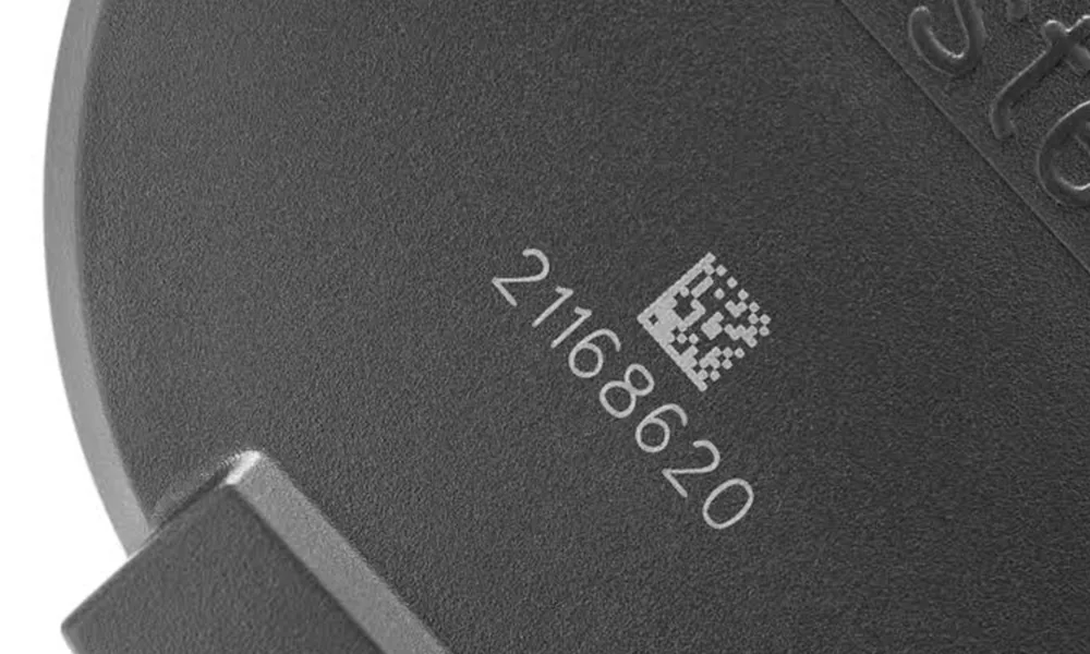
Traceability example
Small codes raise the acceptance bar
Alphanumeric IDs and machine-readable symbols need more than visible contrast. Feature size, edge definition, surface texture, lighting and part position all affect readability, so the actual coated production part should be tested with the real code format.
05 · Target results
What Marking Result Should You Target?
The physical laser effect and the production acceptance result are related, but they are not the same thing. First define what should happen to the coating and substrate, then define how the finished mark will be accepted.
Controlled exposure
Remove enough coating to reveal the intended substrate without digging into the plastic or lifting the surrounding edge.
Check: contrast, line width, edge residue and local deformation.
Low-heat contrast
For heat-sensitive or thin-wall parts, prioritize a readable visual change while limiting discoloration, warpage and gloss shift.
Check: dimensional change and appearance under the agreed lighting.
Repeatable coding
For serial numbers, QR codes or batch identifiers, judge the mark with the actual content, geometry, fixture and inspection setup.
Reader check: confirm decodability under the intended lighting and part position. Verifier check: when a formal grade is required, use the agreed verification method and control module size, quiet zone, lighting, focus and surface condition.
06 · Part geometry
How Do Part Shape, Thickness and Size Change the Process?
The same coating system can behave differently on a flat plaque, a thin molded wall, a curved cover or a recessed marking area. Geometry changes focus, heat flow, fixture stability, field size and fume extraction around the mark.
Thin walls
Thin sections have less thermal mass and can warp, soften or show gloss change sooner. Lower local heat input, shorter dwell and better fixture support may become more important.
Curved surfaces
Surface height changes can move the coating away from best focus, changing spot size, line width and removal consistency. Mild curvature may be manageable; larger height variation can require different optics, positioning or dynamic-focus review.
Recessed or obstructed areas
Ribs, walls, bosses and nearby connectors can restrict the optical path, fixture access or extraction airflow. A mark that works on an exposed coupon may fail when moved into the final molded geometry.
Large or multi-height parts
A larger field changes the optics and may trade marking area against spot size and feature resolution. Multiple heights can require Z adjustment, dedicated fixturing, multiple positions or a 3D marking review.
07 · Laser route screening
Which Laser Route Should Be Tested First?
Fiber, UV and CO₂ can each be relevant in plastic work, but the correct route depends on absorption, coating chemistry, substrate sensitivity, mark size and production geometry. The table is a screening guide, not a promise of final performance.
| Route to evaluate | Why it may fit | Typical risks to test | When to route to a machine review |
|---|---|---|---|
| UV marking | Often worth screening for fine features, sensitive plastics or coating removal where a smaller thermal footprint is needed. | Coating chemistry, resin response, edge residue, source power and cooling requirements. | Fine text, small codes, thin walls, mixed colors or a narrow heat budget. |
| Fiber / MOPA | May fit selected pigmented or additive-containing plastics and some coated surfaces when the absorption window is favorable. | Low contrast, charring, melt or gloss change, coating lift and substrate discoloration. | Existing fiber platform, larger fields, serial marking or a need to compare pulse control. |
| CO₂ | Can be relevant for some organic coatings, films and plastic surfaces when the coating and substrate absorb usefully. | Broad heat input, melting, smoke, edge rounding and inconsistent removal through thickness. | Large-area graphics, film/lacquer systems or a confirmed CO₂-compatible material stack. |
08 · Failure modes
What Are the Common Risks and Failure Modes?
When a coated plastic mark fails, increasing power is rarely the first diagnostic step. Separate coating response, thermal load, positioning and fume behavior before changing the machine configuration.
Weak or uneven exposure
Check coating thickness, pigment, focus, scan overlap and surface height before increasing energy.
Heat deformation
Review pulse behavior, dwell, hatch density, wall thickness and fixture contact. A readable mark is not acceptable if the part moves.
Residue or redeposit
Inspect coating breakdown, extraction position, airflow and post-mark cleaning. Residue can change both appearance and code verification.
Edge lift or charring
Check adhesion, heat spread and scan strategy. A sharper edge may require a different source or parameter window, not only more power.
Read the defect as evidence
For a real sample review, record the coating supplier or formulation if known, the plastic grade, color, wall thickness, target mark, cleaning step, fixture and inspection lighting. These details make a parameter comparison useful; a single “looks good” photo does not.
- Photograph the center and edge of the mark at the same scale.
- Record whether the substrate is exposed, discolored, melted or still covered.
- Check fumes, residue and odor against the planned extraction and filtration path.
- Repeat across representative colors, batches and part locations when production variation matters.
09 · Sample validation
How Should a Coated-Plastic Sample Be Tested and Evaluated?
A coated-plastic test should do more than prove that a visible mark is possible. The sample should represent the finished coating, substrate, geometry and inspection method so the test can identify a usable process window and translate that result into a defensible machine configuration.
Material record
Resin or grade, coating/ink/lacquer and adhesive formulation if present, color, thickness, cure state, batch variation and available SDS information.
Mark definition
Logo, text, code, line width, minimum character, location, contrast target and any depth or tactile requirement.
Acceptance plan
Visual and dimensional criteria, reader check or formal verifier method, cleaning/handling test, cycle target and reject definition.
What should a useful sample report show?
A useful report should connect the visible result to the machine decision. It does not need to disclose every proprietary parameter, but it should show enough evidence to explain why one route is preferred over another.
Surface result
Whether the coating is removed, modified or still present; substrate condition; edge lift; residue; discoloration; gloss change and local deformation.
Readability result
Minimum useful character or feature size, visual contrast under agreed lighting, and code read or formal verification result when applicable.
Repeatability result
Whether the result remains stable across repeated marks, representative colors, different part locations and relevant coating or production batches.
Machine implication
Preferred laser route, required field size and focus tolerance, fixture or vision needs, extraction implications and whether a standard or project-based machine review is appropriate.
10 · Machine configuration
How Is the Final Machine Configuration Chosen?
Once the mark and material are defined, the equipment discussion can be specific without pretending that one standard machine fits every coated plastic surface.
Source and pulse
Compare UV, fiber/MOPA or CO₂ routes against absorption, thermal sensitivity and the target mark.
Optics and focus
Match field size, working distance and focus tolerance to the marking area and part height.
Fixture and vision
Review nests, orientation, part variation and whether vision positioning or a rotary axis is justified.
Extraction and safety
Define capture location, filtration, enclosure, interlocks and operator access for the finished setup.
Machine direction after testing
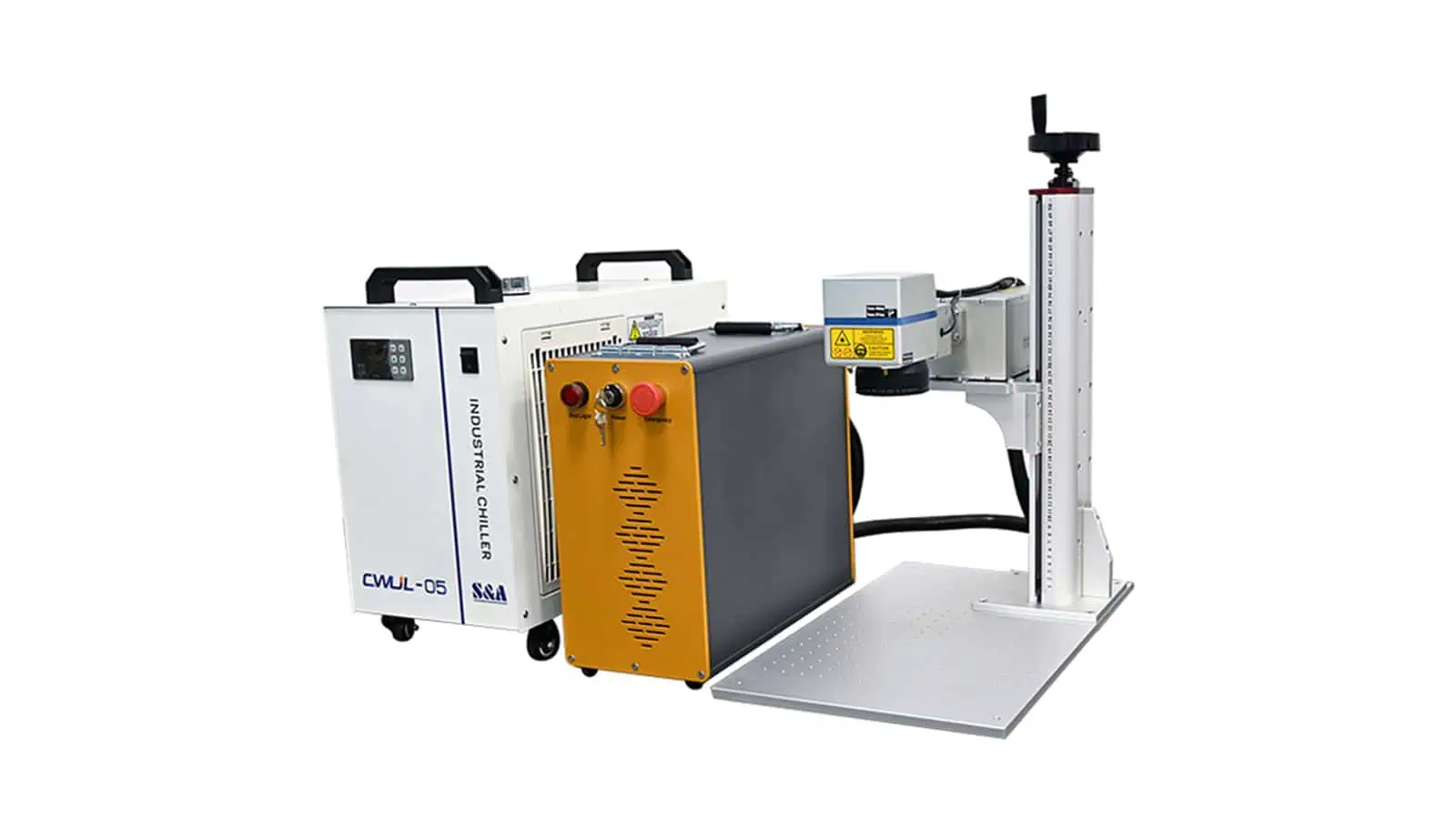
Do not lock the machine before the sample window is proven
The test result should determine source type, optics, cooling, focus tolerance, fixture support and extraction requirements. A UV platform can be a strong candidate for fine or heat-sensitive coated-plastic work, but it should not be treated as the universal default.
What should be confirmed before quotation?
Part and mark inputs
- Plastic grade, coating type, color and finished sample
- Part dimensions, marking-area size and surface geometry
- Artwork, text, code type, minimum feature size and target effect
- Acceptance criteria for appearance, dimensions, readability or durability
Production inputs
- Manual loading, fixture concept or automation context
- Production volume and desired cycle target
- Part variation, number of SKUs and changeover requirements
- Vision, rotary, enclosure, extraction and integration requirements
11 · Practical questions
Coated plastic laser marking FAQ
Can all painted or coated plastics be laser marked?
No. Feasibility depends on the coating chemistry, plastic grade, color, additives, thickness, geometry and target effect. A finished-surface sample test is the reliable way to screen the process.
Is UV always the best choice for coated plastic?
No. UV can be worth evaluating for fine or heat-sensitive work, but fiber/MOPA or CO₂ may fit other coating and substrate combinations. Compare the process window and acceptance result, not a source label alone.
How do I avoid melting or warping the plastic?
Control the thermal budget through pulse behavior, scan speed, overlap, focus, hatch strategy, dwell and fixture support. Validate dimensions and appearance, not only visual contrast.
Why is fume extraction part of the material decision?
Coatings, inks, adhesives and plastics can create formulation-specific smoke, vapors and residue. Review the available SDS first. Unknown formulations, PVC and other halogen-containing materials need EHS or laser-safety assessment before testing; that assessment must determine capture, filtration and waste handling for the intended installation.
Should I send a plastic part or a flat coupon?
Send the finished part when geometry, wall thickness, fixture or marking position affects the result. A flat coupon can support early screening, but it cannot replace a representative production sample.
Next step
Start with a coated-plastic sample review
Share the finished surface, target mark and acceptance criteria. Zhuorui Laser can then review the laser direction, machine configuration and any fixture, vision or extraction requirements that need technical confirmation.