
Carbon-Fiber Composite Marking
Carbon-fiber composite marking is a resin-and-reinforcement problem, not a generic black-material setting. The laser may ablate or discolor the resin matrix, expose carbon fibers, change the surface texture and generate smoke or particles. Confirm the laminate, finish and target effect before choosing a marking machine.
Request a Sample Review Discuss Composite RiskCan Carbon-Fiber Composite Be Laser Marked?
Often yes, but the result depends on the matrix, fiber architecture and surface stack. The process may create a light or dark contrast by removing resin, may reveal the reinforcement pattern, or may damage the laminate if heat is forced into the part. A production recommendation needs a real laminate sample and a defined acceptance limit.
The Matrix and Surface Finish Control the First Visible Response
Epoxy and thermoplastic matrices, together with coatings and surface finishes, can soften, discolor, char, vaporize or leave residue at different thresholds. The visible mark may come from controlled surface modification, selective resin removal or an unacceptable burned zone.
Fiber exposure is a material failure mode
Exposing fibers can be the requested effect for a technical texture, but it can also reduce cosmetic quality, expose loose filaments or affect sealing and downstream bonding.
Smoke and particles are part of the qualification
Resin decomposition, coating removal and carbon dust can affect extraction, optics, cleanliness and operator safety. Review the SDS and filtration path before repeated trials.
What Determines Laser Marking Results on Carbon-Fiber Composite?
“Carbon fiber” describes the reinforcement, not a single laser response. The resin matrix, fiber architecture, surface stack, pigments, fillers and additives can all change what the laser interacts with first, how much contrast develops and how much thermal or surface change remains acceptable.
Resin matrix
Record epoxy, vinyl ester, PA, PEEK, PPS, PEI or another matrix, including cure state, filler and flame-retardant package.
Fiber architecture
Woven, unidirectional, chopped, braided and hybrid laminates expose different fiber paths and can create directional contrast or loose filaments.
Surface stack
Identify clear coat, paint, gel coat, primer, peel ply, printed ink, adhesive residue, sanding and mold texture. The laser may target a layer rather than the laminate body.
Pigments, Fillers and Additives
Colorants, carbon black, flame retardants, mineral fillers and laser-responsive additives can change absorption, contrast, residue and thermal response even when the base resin is similar.
Where Are Carbon-Fiber Composite Parts Used and Why Are They Marked?
Carbon-fiber composites are used where low mass, stiffness, corrosion resistance or a high-performance appearance is valuable. Laser marking is typically requested to identify the part, support traceability, add service information or apply permanent branding without adding a separate label.
| Product context | Typical parts | Why the mark is needed |
|---|---|---|
| Automotive and EV | Interior trim, lightweight covers, brackets, housings and composite panels | Part identification, lot traceability, assembly tracking, service information or branding |
| Aerospace and advanced mobility | Panels, covers, interior structures, UAV components and lightweight subassemblies | Controlled identification, part numbers, maintenance reference and manufacturing traceability where the part specification permits marking |
| Sporting and consumer products | Bicycle components, rackets, helmets, protective gear and performance equipment | Branding, model identification, serialization and cosmetic graphics |
| Robotics and industrial equipment | Robot covers, arms, fixtures, machine panels and lightweight structural components | Serial numbers, asset IDs, service marks and assembly identification |
| Electronics and lightweight enclosures | Device housings, instrument covers, drone parts and compact structural shells | Part numbers, QR/Data Matrix codes, orientation marks and production tracking |
Application boundary: if the part is structural, bonded, pressure-bearing, safety-critical or tightly regulated, the allowable marked area and surface change must come from the part specification and sample validation—not from appearance alone.
What Is Usually Marked on Carbon-Fiber Composite Parts?
The content affects the required feature size, contrast, readability and cycle time. Define the smallest critical feature before choosing the field size and laser configuration.
Traceability codes
Serial numbers, lot or batch codes, date codes, QR codes and Data Matrix codes used to connect the part with production or service records.
Part and assembly identification
Part numbers, model numbers, assembly IDs, position marks, orientation marks and maintenance or service identifiers.
Branding and cosmetic graphics
Logos, product names, decorative graphics and controlled textures where appearance and repeatability are part of the acceptance criteria.
What Marking Result Should You Target?
Define both the physical surface effect and the acceptance result. A mark can look dark or bright but still fail because of exposed fibers, residue, poor code readability, roughness or downstream coating and bonding problems.
Controlled resin modification or removal
Create contrast by changing or selectively removing the surface resin while keeping the reinforcement protected where required. Check edge cleanliness, residue, depth and whether the marked zone remains suitable for sealing, bonding or coating.
Visible fiber texture when it is acceptable
Some noncritical cosmetic or technical parts may accept a visible weave or controlled texture. Define the maximum exposed area, loose-filament limit and whether a sealing or coating step follows.
Readable and durable identification
For logos, serials and 2D codes, judge contrast under production lighting, feature definition, code readability and resistance to the cleaning or abrasion conditions that matter for the finished part.
Acceptance rule: do not approve a setting from appearance alone. Record the visible result together with surface condition, any obvious laminate damage, residue, readability and downstream surface-function requirements.
How Do Part Shape, Thickness and Size Change the Process?
The same laminate can require a different marking setup when the part becomes curved, thin, large or difficult to fixture. Geometry changes focus control, heat flow, access and the way the part must be held during marking.
Flat panels and coupons
Flat surfaces are the simplest condition for focus, hatch filling and side-by-side parameter comparison. A flat coupon is useful for screening, but a finished part is still needed for approval.
Curved or contoured surfaces
Height variation changes focus and spot conditions across the mark. Larger graphics or codes on a contour may need tighter field control, repositioning or a configuration that can compensate for Z-height variation.
Thin walls, edges and bonded zones
Thin sections and edges can be less tolerant of concentrated heat. Keep test marks away from critical joints unless the part specification allows them, and inspect for local distortion, resin recession and delamination.
Large parts and multiple mark positions
As part size grows, the decision shifts toward access, marking field, repositioning, fixture repeatability, Z-axis travel and whether more than one marking position must be reached in a production cycle.
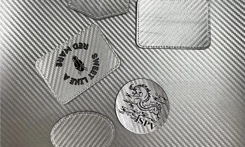
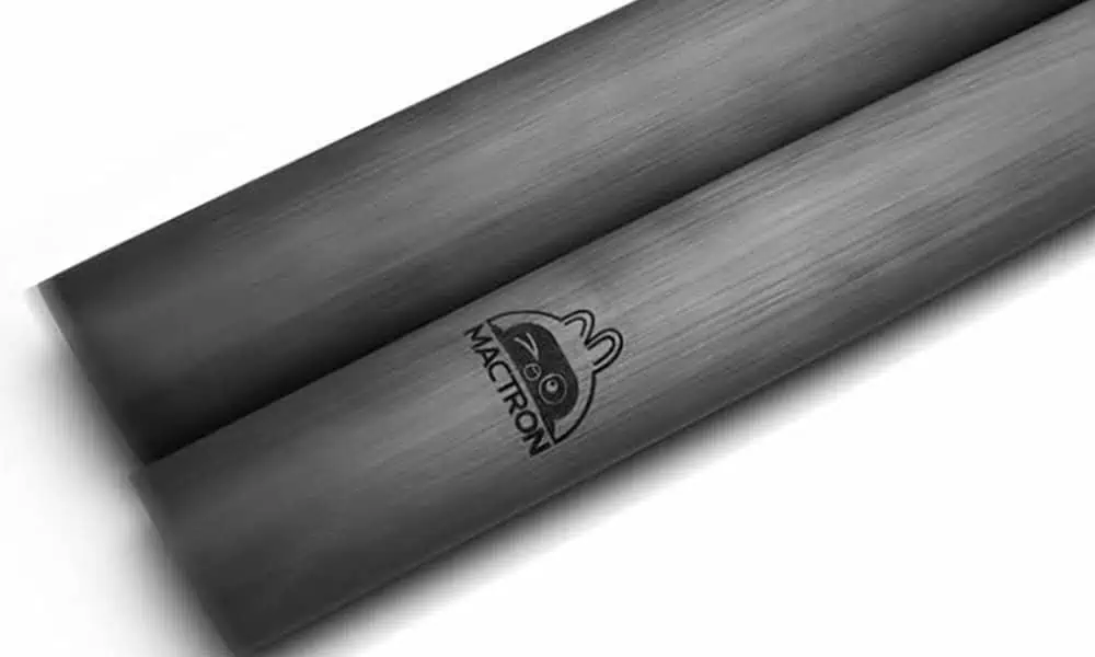
Thickness note: total laminate thickness does not by itself predict the surface response. Surface resin, ply construction, local heat path and the distance from edges or joints are usually more useful test inputs.
| Route | When to test it first or early | What must be checked |
|---|---|---|
| 355 nm UV | Fine codes, small logos, shallow surface interaction or tighter thermal control are priorities on a finished composite surface. | Contrast, resin response, throughput, coating behavior, fiber exposure and whether the UV route provides an acceptable thermal effect with a process window wide enough for production. |
| CO2 laser | Resin or coating removal is acceptable, the target mark is comparatively broad, and the laminate can tolerate a more thermal ablation process. | Charring, delamination, edge melt, excessive resin removal, fiber exposure, smoke load and cleaning requirement. |
| 1064 nm fiber / MOPA | The finished surface contains a coating, pigment, filler or additive that responds at 1064 nm, or an initial test demonstrates a stable dark or textured effect. | Weak contrast on bare resin, localized heating, surface roughness and the temptation to reuse metal parameters on a composite. |
| 532 nm green | A specific project shows useful absorption or thermal behavior at 532 nm and the benefit is demonstrated on the supplied part. | It remains a conditional route; compare it against the simpler UV, CO2 or fiber/MOPA options before committing to a machine platform. |
Test-order rule: start with the route most likely to achieve the required surface effect with the least unacceptable laminate change, then compare the practical process window. Record wavelength, pulse regime, speed, spot size, focus and fill conditions together with the cleaned result.
What Are the Common Risks and Failure Modes?
Most failed trials are not simply “too much power.” They come from a mismatch between wavelength, pulse conditions, surface stack, focus, fill strategy and the acceptance limit of the laminate.
| Failure mode | What it looks like | Why it matters | What to review |
|---|---|---|---|
| Resin charring | Brown or black burnt halo, scorched edges or persistent residue | Can reduce cosmetic quality, contaminate the surface and hide fine code features | Energy density, pulse regime, speed, hatch, number of passes and extraction |
| Excessive resin removal | Deep recess, rough texture or unintended exposure of the reinforcement | May violate surface, sealing, coating or bonding requirements | Pass count, focus, overlap and whether removal is actually required for contrast |
| Fiber exposure or loose filaments | Visible weave, raised strands or loose carbon fibers in the marked area | Can be unacceptable for appearance, handling, sealing or structural requirements | Mark depth limit, resin coverage target and post-mark inspection |
| Delamination or heat damage | Local blistering, lifted layers, softened resin or damage near edges and joints | Can indicate that the process has moved beyond a safe laminate window | Heat accumulation, dwell, geometry, edge distance and laminate construction |
| Poor or uneven contrast | Low readability, gloss-only change or weave-dependent light/dark variation | May fail visual or code-reading criteria even when the surface is not visibly damaged | Wavelength response, coating/pigment, fill direction, focus and inspection lighting |
| Smoke and redeposited residue | Dust, soot, film or contamination around the mark and on nearby optics or fixtures | Affects cleanliness, optical maintenance and sometimes code readability | Extraction capture, filtration, cleaning method and trial duration |
How Should Smoke, Fiber Dust and Laser Hazards Be Controlled?
Composite marking can release resin decomposition products, coating fumes and carbon particulates. The exact matrix, additives and mark depth govern the extraction and filtration requirement.
Confirm the material package
Request the resin grade, SDS, coating or paint information, flame retardant, recycled content and any adhesive or ink on the supplied part.
Control fumes and particles
Plan local exhaust, filtration, residue handling and optical protection before repeated trials. Carbon dust can contaminate lenses and fixtures as well as the workspace.
Enclose the laser source
1064 nm, UV and CO2 beams may be invisible or outside normal visual response. Control direct beam, specular reflection and diffuse reflection, including paths created by curved, coated or tilted workpieces. Guard the cell, verify interlocks and emergency stop, and stop automatic motion before access or abnormal recovery.
Installation safety: the final machine and installed cell still require a documented review of laser classification, guarding, extraction and workplace risk. Document beam paths, reflected-light checks, access conditions, automatic-fault shutdown and filter/residue handling for the installed cell.
How Should a Carbon-Fiber Sample Be Tested and Evaluated?
Use a representative coupon for route screening, then confirm the process on a finished production part with the same surface, geometry and acceptance limits. The test record should be detailed enough to explain why a particular machine configuration is selected.
| Step | What Zhuorui needs | Decision output |
|---|---|---|
| 1. Identify construction | Resin, fiber type, architecture, ply schedule if available, thickness, cure state, supplier/grade information and production surface condition | Material risk map and whether the laser is primarily interacting with a coating, resin-rich layer or the composite surface itself |
| 2. Define the mark | Logo, serial, QR/Data Matrix, part number, smallest feature, marking area and required contrast or appearance | Feature-size requirement and target physical surface effect |
| 3. Screen laser routes | Candidate UV, CO2, fiber/MOPA or green tests with wavelength, pulse regime, speed, focus and fill conditions recorded | Shortlist of laser route and stable parameter window |
| 4. Screen visible surface and laminate damage | Resin change/removal, mark depth, fiber exposure, loose filaments, visible delamination, heat-affected zone, char, roughness, smoke and residue | Pass/fail evidence for surface condition and visible-damage screening; structural acceptance requires the inspection or test method specified for the finished part |
| 5. Verify readability and durability | Code reading or visual inspection plus the relevant wipe, abrasion, cleaning-agent, humidity, thermal or UV exposure checks | Evidence that the mark still meets the user’s real acceptance criteria after handling or environmental exposure |
| 6. Transfer the proven process to production | Part geometry, fixture, marking positions, cycle-time target, vision need, extraction, cleaning, loading method and data workflow | Machine source, lens/field, motion, fixture, enclosure, extraction and automation configuration for quotation |
Approval rule: the final machine should be based on the tested process window plus the real part-handling requirement. A visually acceptable coupon alone is not enough to lock the production configuration.
How Is the Final Laser Marking Machine Configuration Chosen?
The sample test identifies a workable laser process. The finished part and production requirement then determine the field size, focus control, fixture, extraction, safety structure and any vision or automation needed around that process.
| Production input | Configuration decision it affects | What should be confirmed before quotation |
|---|---|---|
| Proven wavelength and process window | UV, CO2, fiber/MOPA or another verified source route; pulse behavior and practical power range | The route must reproduce the required result without unacceptable char, delamination or fiber damage on the real part |
| Mark size and smallest feature | Lens, marking field, spot/feature requirement and whether repositioning is acceptable | Actual marking area, smallest text or code module and readability criteria |
| Part shape and height variation | Z-axis travel, fixture, part orientation, rotary or focus-compensation requirement | Drawing, dimensions, mark location, curvature and access around the marked area |
| Smoke, dust and cleaning load | Extraction capture, filtration, enclosure protection and optical-maintenance plan | Material/SDS information, coating stack and the amount of ablation demonstrated during testing |
| Loading, positioning and inspection | Manual fixture, custom fixture, vision alignment, multiple stations or automation review | Part presentation, orientation tolerance, changeover frequency and whether the mark must be inspected automatically |
| Production rate and data workflow | Marking strategy, controller/data interface, loading concept and automation level | Required output per hour, marking content, number of marked positions and what data must be sent to or received from the marking system |
For an RFQ: send the finished part or representative sample, material/resin information if available, surface coating, part dimensions, mark location and content, smallest required feature, acceptance criteria, expected quantity or cycle-time target, loading method, and any vision, data or automation requirement.
Carbon-Fiber Composite Laser Marking FAQs
Can carbon fiber be laser marked?
Many carbon-fiber composites can be evaluated, but the response is controlled by the resin matrix, fiber architecture, coatings and target effect. A real laminate sample is the approval gate.
Will laser marking expose the carbon fibers?
It can. Resin ablation may reveal the weave or individual fibers, especially when depth or heat is increased. Whether that is acceptable depends on the part function, surface specification and the customer’s acceptance limit.
Is CO2 or UV better for carbon-fiber composite?
CO2 may suit broader resin or coating removal, while UV may suit finer or heat-sensitive surface work. Neither is universal; matrix, finish, speed and smoke load must be compared on the supplied part.
Can a fiber laser mark carbon fiber?
Sometimes, particularly when a coating, pigment or additive responds to 1064 nm. Bare resin may show weak contrast or localized thermal damage, so metal settings must not be reused without testing.
What smoke and dust should be expected?
Resin decomposition, coating removal and carbon particulates may be generated. Provide the SDS and review local exhaust, filtration, residue handling and optical maintenance before repeated trials.
Can laser marking weaken a carbon-fiber composite part?
It can if the process removes too much resin, exposes or damages fibers, creates delamination, or heats a critical area beyond the part’s allowable limit. Structural or safety-critical parts should be evaluated against the actual drawing, marked-zone restrictions and sample-test results before production approval.
Send the Actual Part Before Locking the Machine Configuration
Provide the finished part or representative sample, resin or material information if available, coating, dimensions, mark position and content, smallest feature, acceptance criteria, expected production rate, loading method and any vision, data or automation requirement. Zhuorui Laser can use those inputs to plan the sample test and narrow the final machine configuration.