
Mobile Phone Parts Laser Marking
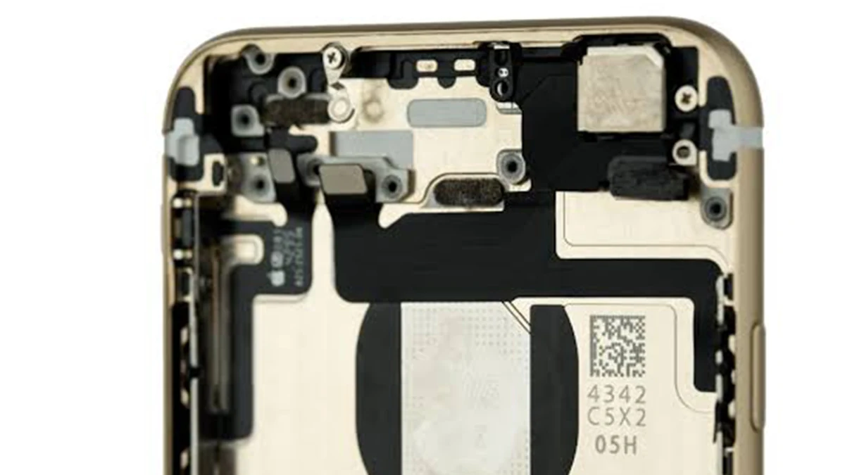
Permanent identification for phone frames, brackets, housings and internal parts — brand, model, IMEI, serial and batch codes — is typically placed on internal or approved low-visibility faces so traceability can be maintained without unnecessary changes to customer-facing surfaces.
This page covers the industry-task view for selecting a mobile phone laser marking machine: what gets marked, which surfaces are approved for marking, how stepped or irregular geometry changes fixturing and configuration, and what must be validated on a real sample before purchase.
Mobile Phone Parts Laser Marking at a Glance
Laser marking is commonly evaluated for permanent identification on mobile phone frames, brackets, housings, trays, shields and other internal components. Typical jobs include brand or model identification, part and lot numbers, IMEI or serial information where specified, and compact Data Matrix or QR codes for traceability.
The useful starting point is not simply “metal or plastic.” Define the exact material and surface, the approved marking zone, the required visual or code result, the smallest feature to be marked, the part geometry and positioning method, and the required production cycle. Those inputs determine which laser route to test first and what must be verified before the final machine configuration is fixed.
Bare aluminum, anodized aluminum, stainless steel, titanium and plastic grades should be treated as different sample-test conditions because their surface response and thermal sensitivity differ. For PCB assemblies or individual electronic components, see the dedicated PCB / PCBA and electronic components application pages.
Which Mobile Phone Parts Are Commonly Laser Marked?
The part family matters because its material, wall thickness, available marking zone and geometry change how the job should be tested and fixtured.
Metal frames, brackets and chassis
CNC-machined phone frames, chassis pieces and brackets are often aluminum, with stainless steel or titanium used on some designs. These parts may provide relatively stable marking zones, but anodized or cosmetic surfaces, stepped faces and thin walls can make the real marking window very different from a flat metal test coupon.
Housings and internal covers
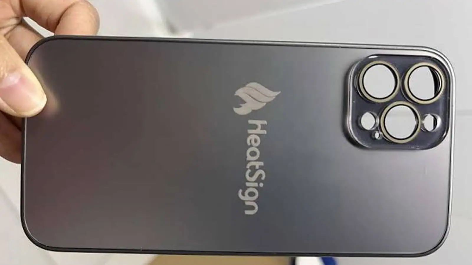
Metal or plastic housings and internal covers can carry product identification or traceability marks. Exterior surfaces are usually more tightly controlled for appearance, so the approved mark zone must come from the product drawing rather than from convenience at the marking station.
Trays, shields and small internal parts
Card trays, shields, small brackets and other internal parts often have limited mark area. Small characters or compact 2D codes make focus, contrast, positioning repeatability and reader access more important than total mark area.
| Part family | Typical marking role | Common constraint to check |
|---|---|---|
| Metal frame / chassis / bracket | Product identification and traceability | Surface finish, stepped height, cosmetic keep-out zones |
| Housing / internal cover | Brand identity, serialization or process identification | Visible-vs-hidden zone, coating or plastic formulation |
| Plastic bracket / tray | Part, assembly and lot identification | Heat sensitivity, small mark area, position repeatability |
| Shield / card tray / small metal part | Lot, traceability or process mark | Small code size, flatness, scanner access after marking |
Why Are Mobile Phone Parts Marked?
The marking purpose should be defined before the laser route. A logo, a fixed part number and a serialized traceability code create different requirements for content control, verification and production data.
Identification and traceability
- Product identification — brand, model, part number or customer part number where the drawing requires it.
- Lot and serial traceability — batch, serial, IMEI or 2D-code information when the part must be linked to production records.
- Assembly identification — polarity, orientation, process or station marks that help distinguish parts during manufacturing.
Production and quality control
- Downstream verification — machine-readable codes can be scanned after marking to confirm the value and readability.
- Process genealogy — changing data can be associated with a line, batch or production record when the manufacturing system requires it.
- Controlled cosmetic use — exterior logos or visible identification are valid only where the product drawing defines the location and appearance requirement.
If the mark contains changing serial, IMEI or code data, define where that value comes from and whether it must be verified after marking. That data requirement can affect the marking station as much as the laser source itself.
What Is Usually Marked on Mobile Phone Parts?
Content type, code size and the available marking zone determine the smallest feature the process must produce reliably. Fixed text, changing serial data and compact 2D codes should be treated as different production requirements.
IMEI, serial numbers and batch codes
IMEI and serial numbers can be marked as readable text plus a code symbol on the same part when the product specification requires it. Character height and line width must fit the available approved zone, and the reading environment after assembly matters: a code that is covered, too small or too low in contrast will not survive the final inspection. Batch and lot codes add a production-time dimension — the same part family can carry a changing code value per batch, which points to a data interface rather than a fixed text job. IMEI number allocation and marking compliance remain the responsibility of the brand owner and the applicable product requirements; the marking station must reproduce the assigned content correctly within the specified zone.
Data Matrix / QR and small-character requirements
Data Matrix and QR symbols are common on frames, shields and trays because they hold more data than text in a small area. The achievable symbol size and contrast depend on the optical setup and on the material and surface state — for example, anodized aluminum, bare aluminum and plastics should be evaluated as different sample conditions. Position accuracy also matters: if the code must be read by a fixed scanner or compared against a database, the mark position must repeat within the reader’s tolerance, which is a fixturing question as much as a marking question.
Where a code must be scanned downstream or matched to production data, read-back verification should be part of the acceptance requirement. Use the intended scanner or verifier to confirm the marked value and readability; add contrast or character inspection when the customer specification requires it. The result remains sample-dependent and should be confirmed on the actual part.
What Determines Laser Marking Results on Mobile Phone Parts?
Two phone parts that look similar can require different settings or even a different laser route. The result is controlled by the complete part condition, not by the material name alone.
| Variable | Why it changes the result | What to confirm |
|---|---|---|
| Material and grade | Aluminum, stainless steel, titanium, ABS, PC and other materials interact with the laser differently. | Actual material or resin grade where available |
| Surface condition | Bare, anodized, painted, coated, polished or textured surfaces can produce different contrast and surface change. | Finish, coating, color and cosmetic requirement |
| Wall thickness / thermal sensitivity | Thin metal and plastic parts can accumulate heat, discolor or distort before the desired mark is achieved. | Thickness around the mark zone and allowable surface change |
| Mark content and minimum feature size | Small characters and compact 2D cells require more optical resolution and stable focus than a large logo. | Smallest character, line or code-cell requirement |
| Marking zone | Exterior, hidden, recessed, functional or keep-out areas impose different cosmetic and access limits. | Drawing-approved zone and post-assembly visibility |
| Height, curvature and cavity depth | Z-height variation and beam access affect focus consistency and whether one setup can reach the whole mark. | Height variation, angle, cavity depth and available access |
| Position tolerance | Tight location tolerance increases the importance of fixture repeatability or vision correction. | Allowed X/Y/rotation error and datum method |
| Target result | Light contrast, dark contrast, black appearance, shallow marking, engraving or coating removal can point to different process windows. | Approved visual, code and surface acceptance criteria |
| Production requirement | Loading, code generation, verification and handling can dominate full cycle time and system design. | Parts per hour, batch size, loading method and data flow |
These variables should be frozen as the sample-test input. If the same part exists in several finishes or resin colors, test them as separate conditions rather than assuming one parameter set will transfer unchanged.
What Marking Result Should You Target?
A useful sample request defines the result before it defines the machine. “Permanent mark” is too broad; the target should describe what the mark must look like, how it will be read and what surface change is acceptable.
Visual and identification result
- Appearance — light, dark, black, high-contrast or another drawing-approved visual effect.
- Human-readable content — required character height, line width and legibility under the specified inspection conditions.
- Code result — Data Matrix / QR size, intended reader and any required read-back or verification criterion.
Surface, function and durability result
- Surface condition — acceptable roughness, discoloration, coating change or engraving depth where specified.
- Functional protection — no unacceptable change to sealing, mating, contact or other drawing-controlled surfaces.
- Durability — abrasion, sweat, solvent, humidity or temperature checks only where the product specification requires them.
Once these acceptance targets are defined, laser selection becomes a testable engineering question: which route can reach the required contrast, code readability and surface condition without creating unacceptable heat or cosmetic damage?
Where the Mark Goes: Visible vs Hidden Zones
Position is a design decision as much as a laser decision. For identification and traceability marks, hidden or assembly-covered faces are usually preferred when the product drawing reserves customer-facing surfaces for cosmetic requirements. Exterior marking should be evaluated only when the design explicitly calls for it and defines its own appearance and durability acceptance criteria.
Visible exterior surfaces need explicit approval
Exterior surfaces — the outer face of the frame, the visible side of the housing, decorative or anodized surfaces — are commonly controlled by cosmetic specifications. Laser processing changes the local surface response and may affect appearance, roughness or scratch-resistance acceptance, so these areas should follow the product drawing and finish specification. When exterior marking is genuinely required, it is a design decision with its own acceptance criteria, not a default.
Hidden and assembly-covered zones
- Inner face of the frame — a common target for brand, model and traceability content when the exterior is reserved for cosmetic requirements.
- Inside of the housing / hidden cover — can carry serialized codes and process marks, protected from daily handling.
- Back of a bracket / inner side of a shield — often flat, stable and out of the customer’s line of sight.
Controlled or keep-out zones
- Customer-facing exterior surfaces — use only when the drawing explicitly permits marking and defines acceptance criteria.
- Decorative or anodized surfaces — laser processing changes the local surface and may affect cosmetic or scratch-resistance acceptance.
- Functional or sealing areas — surfaces that mate, seal or carry components must follow drawing-defined keep-out rules.
- Zones covered later in assembly — if the mark will be covered, confirm it can still be scanned, or move it.
Positioning and part presentation
Where the mark lands depends on how the part is presented to the laser. A flat hidden face on a tray is straightforward; a stepped frame or a curved bracket may need a fixture, a rotary axis or vision positioning so the focus and the mark position stay consistent. For alignment and positioning methods, see the vision positioning solution; for cylindrical features that rotate, see the rotary marking solution.
How Do Geometry, Fixturing and Positioning Affect the Process?
Phone parts are rarely flat plates. Frames have stepped faces, housings have deep cavities, brackets are thin and irregular — and each shape changes how the part must be held and how the laser reaches the mark zone.
Stepped frames and deep cavities
A stepped frame has marking zones at different heights. A flat-field laser can mark a plane reliably, but a step means either a second setup or a dynamic-focus / 3D approach when the height difference exceeds the usable focus range — and the right answer depends on the step height and the mark position. Deep cavities on housings or frames raise a reachability question: the laser head must reach the zone without the cavity wall blocking the beam, which affects working distance and field-size choices.
Thin-walled and irregular brackets
Thin walls and thin-walled brackets are more sensitive to heat input and to clamping stress. The fixture must hold the part without distortion, and the parameter window should be evaluated with the real part rather than a flat test coupon, because wall thickness changes how heat accumulates. Irregular shapes often need a custom or conformal fixture to keep the mark zone in focus and in position for every part.
Random placement and vision positioning
Vision-guided marking can reduce dependence on precision locating fixtures when the main variation is the part’s X/Y position or rotation. The camera locates each part and the software corrects the mark position within the available field. The part still needs stable presentation, and height variation, tilt, deep cavities or changing focus may require dedicated fixturing, autofocus / 3D control or another setup. This approach is useful for flexible or mixed-part phone-component marking when tray positions cannot be held repeatably. The integration approach is covered by the vision positioning solution; for round or stepped features that rotate, the rotary marking solution applies.
| Part geometry | Typical fixturing | Configuration direction |
|---|---|---|
| Flat hidden face (bracket, tray) | Dedicated tray or simple jig | Standard desktop or split machine |
| Stepped frame, multiple heights | Step-specific fixture or second setup | Evaluate 3D dynamic focus if the step height exceeds the usable focus range |
| Deep cavity in housing | Fixture that exposes the cavity | Working-distance / field-size review, possible 3D |
| Thin-walled irregular bracket | Conformal / low-stress fixture | Parameter-window review on the real part |
| Random placement | Stable presentation plus vision-guided positioning | Vision CCD machine / vision solution |
Which Laser Direction to Evaluate First
Phone parts span a wide material range, so there is no single “phone laser”. The starting direction follows the material and surface of the part being marked — and the final choice depends on the target contrast, geometry and sample results.
Metal frames and anodized parts
For aluminum frames, stainless steel brackets and titanium parts, a Q-switched fiber laser (about 1064 nm) is often the first direction to evaluate and is a common starting point for metal identification. Anodized aluminum behaves differently from bare aluminum because the anodic layer changes how the surface responds; treat it as a separate sample condition and use the anodized aluminum guidance when defining the test. When white or light-contrast marks are needed, MOPA fiber can be worth evaluating: its wider pulse-control window changes heat input and surface response. This is a conditional direction, not a guarantee.
Plastic brackets and heat-sensitive parts
For dark or heat-sensitive plastics — ABS, PC and similar grades — UV lasers (around 355 nm) are often the first direction to evaluate because the shorter wavelength can reduce the thermal load on thin or heat-sensitive parts. Plastic behavior depends heavily on resin grade, colorants and additives, so the actual grade should be sample-tested; the ABS and polycarbonate guidance can help define the starting route.
When contrast, depth or black-mark goals change the choice
If the goal is a deep or engraved mark, a black mark on a light surface, or a coating-removal effect, the direction can change. These goals are material- and surface-specific: a light-on-dark result on anodized aluminum and a black mark on stainless steel are different targets that may point to different parameter windows or sources. The right way to decide is a sample test on the actual part, not a general rule.
| Part material / surface | Starting direction | Material page for detail |
|---|---|---|
| Aluminum frame, bare | Q-switched fiber (1064 nm); evaluate MOPA when the target effect benefits from its pulse-control range | Aluminum |
| Anodized aluminum frame | Fiber / MOPA, anodic-layer-specific | Anodized Aluminum |
| Stainless steel bracket | Fiber; black-mark route evaluated by surface and target | Stainless Steel |
| Titanium part | Fiber / MOPA | Titanium |
| ABS / PC bracket, dark or heat-sensitive | UV (355 nm) often first | ABS / PC |
What Are the Common Mobile Phone Part Marking Failure Modes?
A good sample test should try to expose the likely production failures, not just produce one attractive mark. Most problems can be traced to surface response, focus, positioning, heat input, access or data control.
| Failure | Typical cause to investigate | What it may change |
|---|---|---|
| Low or inconsistent contrast | Surface finish, coating, material variation, focus or unstable parameter window | Laser route, parameter window, surface-specific recipe |
| 2D code will not read reliably | Cell size, contrast, focus, surface texture, position or reader setup | Optics / field size, code size, process window, verification setup |
| Mark position shifts | Fixture repeatability, tray tolerance or random part rotation | Fixture design, datum strategy or vision positioning |
| Different Z heights give different results | Stepped geometry exceeds usable focus range | Second setup, Z adjustment or 3D dynamic focus |
| Heat discoloration, melting or distortion | Thin wall, heat-sensitive resin or excessive local energy | Laser route, pulse control, speed / energy window, fixture support |
| Cosmetic surface rejected | Mark placed on a controlled exterior finish or appearance target not defined before testing | Marking zone, target result or process route |
| Beam cannot reach the zone consistently | Deep cavity, side wall, angle or insufficient working distance | Fixture orientation, optics, working distance or multi-axis approach |
| Correct-looking code carries the wrong data | Part identity, serial data or verification flow is not controlled | Data interface, scanner verification and reject logic |
If a sample fails, record the failure against the actual material, surface, geometry and process condition. That makes the next test meaningful and prevents a machine configuration from being frozen around a result that only worked on one ideal sample.
How Does Mobile Phone Part Marking Fit Into Production?
Production readiness is the complete sequence from part presentation to verified output. Scan time is only one element; handling, identification, positioning, data exchange, inspection and reject flow can determine the final workstation design.
Handling and positioning
The production cycle starts with loading the correct part and presenting the approved mark zone at a repeatable position and height. Tray-fed parts may use a dedicated jig; mixed or less repeatable presentation may justify vision positioning. Stepped or recessed parts can require part-specific fixtures, Z adjustment or a different optical arrangement before marking begins.
Data, marking and verification flow
For fixed logos or part numbers, the marking job may use a controlled recipe. For changing serial, IMEI, lot or 2D-code data, define where the value is generated, how the correct part is associated with that value, and whether the marked result must be read back. A typical controlled flow is part / recipe identification → receive or generate mark data → position → mark → scan or inspect → compare with expected data → pass or reject. Where database or MES connectivity is required, the traceability and data integration solution provides the deeper integration context.
Cycle time, reject handling and automation
Measure the full cycle including loading, locating, marking, verification and unloading. If a failed read or failed position check occurs, define whether the part is stopped, reworked or routed to a reject path rather than allowing it to continue unverified. Manual or semi-automatic tray loading is suitable for many jobs; higher volume or line-based production can justify the automatic marking cell or, where the process truly involves continuously moving parts, the flying / online marking route.
How Should a Mobile Phone Part Sample Be Tested and Accepted?
Where the customer or brand specification includes durability requirements, the mark may need to remain readable after handling, moisture, cleaning-agent or temperature exposure. Which checks apply depends on the part, material, mark location and product specification, so validation is defined on real samples rather than assumed.
Abrasion, sweat, solvent and temperature exposure
Depending on the customer or brand specification, validation may include abrasion or scratch testing, sweat or humidity exposure, solvent or cleaning-agent exposure, and temperature cycling. These are example validation categories, not a universal test set for every phone part. The relevant failure mode also changes with the material and surface, so the test method and pass criterion should be defined before the sample is evaluated.
Sample testing: what to prepare and what gets verified
Sample testing is the practical way to confirm contrast, code readability, mark position and durability on the real part. Zhuorui Laser supports sample marking, parameter setup and process review during application evaluation. A real part and a clear mark specification produce a much more useful result than a verbal description. For the sample test, send the part or material sample, a drawing or photo, the required mark content and size, the target effect, production rate and expected volume.
Acceptance dimensions
| Dimension | What is checked |
|---|---|
| Contrast and legibility | Mark readable under the specified lighting / magnification |
| Character and code size | Meets the drawing or code-specification minimums |
| Code readability | Read-back with the intended scanner or verifier when required |
| Position accuracy | Mark position repeatable within the application tolerance |
| Abrasion / scratch | Surface test when required by the customer or brand specification |
| Solvent / sweat / temperature | Exposure test when defined by the application |
| Cycle time | Measured on the real arrangement, including loading |
The acceptance criteria themselves are defined by the customer or brand owner. The useful output from sample testing is a recorded pass / fail result tied to the actual part condition and production requirement, so the accepted process can be translated into the machine, optics, fixturing, positioning and verification configuration. Factory quality control and testing capability are described on the quality control and testing capability page.
How Do Sample-Test Results Determine the Final Machine Configuration?
The final machine should be frozen from accepted sample results and production constraints, not from the material name alone. Each test finding should translate into a specific equipment or integration decision.
| Test or project finding | Configuration decision it informs |
|---|---|
| Q-switched fiber reaches the required metal result with acceptable surface condition | Retain the fiber route and optimize the production parameter window |
| MOPA provides the required appearance or thermal-control window more reliably | Evaluate a MOPA fiber configuration rather than treating it as a parameter-only change |
| Plastic shows unacceptable heat effect with the current route | Review UV or another verified route and retest the actual resin / color condition |
| Small characters or 2D cells need more resolution | Review field size, lens / optical configuration and usable working area |
| Part height variation exceeds the usable focus range | Use a controlled Z setup, multiple setups or evaluate 3D dynamic focus |
| X/Y/rotation variation causes position failures | Improve the fixture / datum strategy or add CCD vision positioning |
| Deep cavity or side wall limits beam access | Change fixture orientation, working distance, optics or motion arrangement |
| Manual loading cannot meet the required full cycle | Evaluate tray indexing, semi-automatic handling or an automatic cell |
| Changing serial / IMEI / code data must be verified | Add data interface, scanner / vision verification and pass / reject logic as required |
| Several phone-part variants share one station | Define changeover fixtures, recipes, vision strategy and operator / system part selection |
| Durability or cosmetic acceptance fails | Return to process-route and parameter testing before freezing the machine configuration |
The result is a project specification that connects laser source + optics / field + focus strategy + fixture or vision + handling + verification / data + safety enclosure and, where the material or process requires it, fume extraction or ventilation. A sample that only proves “the laser can make a mark” is not enough to freeze a production machine.
Frequently Asked Questions
Can laser marking damage the visible exterior surface of a phone frame?
Yes, laser processing changes the local surface. For traceability marks, customer-facing surfaces are commonly treated as controlled zones unless the product drawing explicitly requires exterior marking and defines its appearance and durability acceptance criteria.
Do stepped frames or deep cavities need special fixturing?
Often yes. A stepped frame has marking zones at different heights, and a deep cavity raises a reachability question, so a step-specific or cavity-exposing fixture is usually needed. When height variation exceeds the usable focus range, a 3D dynamic-focus approach may be worth evaluating.
Can marking be integrated into a tray-fed or inline assembly line?
Yes. Tray-fed manual or semi-automatic marking is common, and higher volume can justify inline or flying marking and automatic loading cells. Integration feasibility — cycle time, positioning and data interface — is evaluated as a project, and the relevant solution pages describe the approaches.
Why does marking contrast differ between anodized aluminum, bare aluminum and plastic?
Because the material and surface absorb and respond to the laser differently. The mechanisms are explained on the dedicated anodized aluminum, aluminum, ABS and polycarbonate pages, and the realistic result for a specific part must be confirmed by sample test.
Can IMEI and serial numbers be laser marked directly on metal frames?
They can be marked when the product specification assigns that content to the metal frame. The achievable character size, contrast, position and durability depend on the material, surface and optical setup, so the specific requirement should be validated on the real part.
Can the mark survive abrasion, sweat and solvents during daily use?
It depends on the material, surface, laser parameters and the acceptance method. Where those exposures are part of the customer or brand specification, they should be included in sample validation with defined test conditions and pass criteria.
Send the Part, Target Result and Production Requirement
For a useful sample evaluation, provide the actual phone part or representative material, material / surface information, drawing or approved mark zone, mark content and minimum size, target visual or code result, positioning tolerance, loading method, required cycle or output, and any scanner, durability or data requirement. Zhuorui Laser can then evaluate the starting laser route, fixture / positioning needs and sample acceptance plan before the machine configuration is finalized.
For any phone-part marking workstation, the equipment review includes laser safety controls for the specific machine configuration. Enclosure, interlock and extraction requirements must be assessed on the complete system rather than inferred from the laser source alone.