Zhuorui Laser / Technology Guides / UV Laser Marking Technology
Laser Technology Guide
UV Laser Marking Technology
UV laser marking is most valuable when a marking problem cannot be solved simply by increasing laser power.
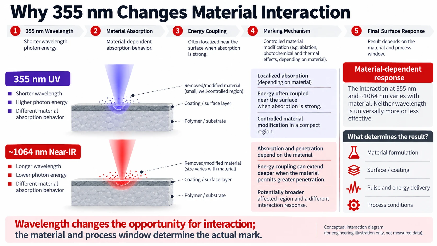
Industrial UV marking systems commonly operate at 355 nm, a substantially shorter wavelength than the near-infrared output used by conventional fiber marking lasers. That difference can change how a material absorbs the beam, how tightly the beam can be focused, how energy is deposited near the surface, and ultimately whether the process produces useful contrast, clean ablation, excessive heat, or no acceptable mark at all.
For heat-sensitive polymers, electronic materials, coatings, thin films, glass, ceramics, and very small traceability features, those differences can create a useful process window. For deep metal engraving, high-material-removal tasks, or many routine metal identification jobs, the same UV system may offer little practical advantage over a fiber laser.
The useful engineering question is not whether UV is more advanced than fiber or CO2. It is whether 355 nm creates a better and more stable interaction with the actual material while still meeting the required mark quality, cycle time, and production conditions.
What Is UV Laser Marking?
UV laser marking uses ultraviolet laser radiation to create a controlled optical, chemical, thermal, or physical change in a material.
In many industrial solid-state UV systems, 355 nm light is not generated directly at the original laser wavelength. A near-infrared solid-state laser can produce a fundamental wavelength around 1064 nm, which is then converted through nonlinear optical crystals. Frequency doubling produces 532 nm light, while a further nonlinear mixing stage can produce the third harmonic at 355 nm. Coherent describes this frequency-tripling architecture in its industrial UV laser technology documentation. Coherent: Nonlinear Crystals
That detail matters because UV is not simply a fiber laser with lower power. It is a different optical architecture delivering a different wavelength to the workpiece.
Once the beam reaches the part, the mark may result from several mechanisms. Depending on the material and process conditions, the laser may change pigment chemistry, modify molecular structure, remove a thin coating, ablate a surface layer, produce localized discoloration, or create shallow material removal.
TRUMPF, for example, distinguishes plastic laser marking mechanisms such as color change and layer ablation, and notes that the result depends on the plastic, wavelength, and additives rather than on the material family name alone. TRUMPF: Laser Marking Plastics
UV laser marking is primarily a wavelength-material interaction problem, not a wattage problem.
Why Does the 355 nm Wavelength Change Material Interaction?
A laser can only create the intended process when enough of its energy couples into the target material in the right location. When light reaches a workpiece, some energy can be reflected, transmitted, scattered, or absorbed. The absorbed part is what drives the material response.
Changing wavelength changes those proportions.
This is especially important for polymers. TRUMPF notes that the macromolecular structure of plastics tends to absorb in particular spectral regions, while pigments, carbon black, dyes, and other additives can have different absorption spectra. It specifically identifies 532 nm and 355 nm sources as wavelengths that can expand the range of plastics that can be marked effectively compared with conventional near-infrared marking wavelengths. TRUMPF: Laser Marking Plastics
This explains why two parts both labelled PC or ABS may not respond identically. One may contain a pigment or additive package that couples strongly with 355 nm and develops clean contrast. Another nominally similar formulation may require a different energy level or even a different wavelength.
Absorption is only the beginning
It is tempting to explain UV marking by saying that UV photons break molecular bonds instead of heating the material. That is too absolute.
Research on 355 nm processing of polyimide shows that photochemical and photothermal mechanisms can coexist. Experiments and models on 355 nm polyimide processing describe different relative contributions depending on the material and process regime. Earlier work also warns that thermal effects in UV polymer processing cannot simply be neglected. ScienceDirect: 355 nm Polyimide Processing Study
This changes how cold marking should be understood. It does not mean zero heat. A more useful engineering interpretation is that 355 nm can, for suitable materials and operating conditions, produce the required surface change with less unwanted thermal influence on the surrounding material than a process that relies more heavily on bulk heating.
If pulse energy density, overlap, repeated passes, or accumulated energy becomes too high, the same UV process can still create melting, carbonization, deformation, cracking, debris, or an unnecessarily large affected zone.
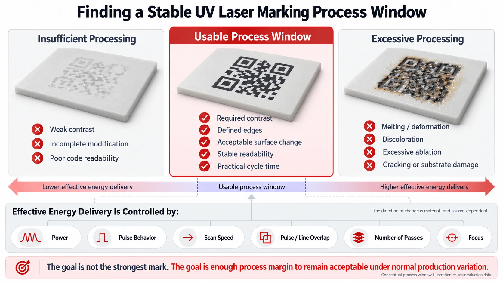
The correct question is therefore not whether UV is cold. It is whether the combination of wavelength and process conditions produces the required interaction before unacceptable thermal or ablation damage begins. That interval is the useful process window.
Why Can UV Support Fine Marking With Lower Thermal Impact?
The fine-marking capability of UV is often reduced to one statement: shorter wavelength means a smaller spot. The direction is correct, but the real optical relationship is more useful.
For a focused laser beam, the diffraction contribution to spot size depends on wavelength, beam quality (M2), focal length, and incoming beam diameter. Optical aberrations introduce an additional limitation. Edmund Optics describes this relationship explicitly: shorter wavelength and shorter focal length can reduce the diffraction-limited spot, while beam quality, beam diameter, and aberration also affect the final result. Edmund Optics: Laser Beam Expander and Focus Relationships
So 355 nm gives an optical advantage, but it does not independently define resolution.
Consider two systems. One uses 355 nm but a large marking field, longer focal length, imperfect beam quality, and loose focus control. Another uses a longer wavelength but a well-designed small field, good beam quality, and tightly controlled part height. It is not valid to conclude from wavelength alone that the first system must produce the finer production mark.
There is also a second distinction: optical spot size is not the same as the final material feature size.
Even when the focused beam is small, the affected area can become larger if the material receives excessive energy or heat accumulates from closely spaced pulses or repeated scans.
For fine Data Matrix cells, micro-text, thin coating removal, or narrow lines, the production result therefore depends on two linked conditions: the optical system must place energy into a sufficiently small region, and the material process must keep the affected region close to that optical scale.

What Are the Main Advantages of UV Laser Marking?
The strongest advantage of UV is not high precision by itself. Its real value appears when the short wavelength, absorption behaviour, optical focusing potential, and allowable material damage align with the application.
For heat-sensitive polymers, this can mean producing contrast before the surrounding material begins to melt, foam, char, or distort.
For coated components, it can mean removing or modifying the upper layer while maintaining enough process separation from the substrate underneath.
For compact electronic components, it can mean creating a readable identifier while limiting the affected zone around sensitive structures.
For high-density traceability codes, it can mean maintaining smaller feature geometry without enlarging the mark simply to make it readable.
UV can create additional separation between the desired marking mechanism and an unwanted damage mechanism.
That separation is not guaranteed. It has to exist for the actual material. A polymer formulation that absorbs 355 nm poorly may offer no such advantage. A coating and substrate with similar ablation behaviour may provide too little margin for selective removal. A high-speed production target may force the process outside the quality window.
An advantage exists only when it survives the actual production constraints.
Which Materials Are Best Suited to UV Laser Marking?
Material suitability should not be reduced to a list of green check marks.
| Material / Surface | Why UV Is Often Evaluated | Typical Objective | Main Validation Boundary |
|---|---|---|---|
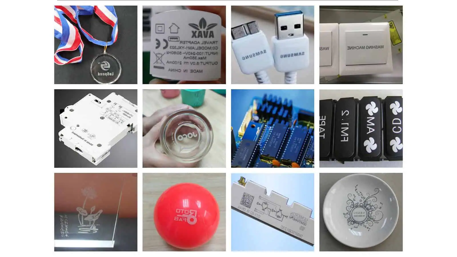
| Plastics / polymers | 355 nm may couple more effectively with the polymer or its additives and can provide a lower-damage process window. | Contrast marking, fine text, Data Matrix, small logos | Exact resin, pigment, filler, additive package and colour |
| PCB / electronic materials | Small-feature potential plus useful interaction with polymers, solder masks and thin material stacks. | Traceability, coding, selective layer processing | Stack-up, copper below the surface, encapsulant, solder mask |
| Glass | UV can support localized surface processing and fine features. | Identification, codes, surface modification | Glass chemistry, stress state, accumulated energy, crack formation |
| Ceramics | Localized interaction can produce contrast or controlled surface modification. | Identification and traceability | Ceramic composition, glaze, surface finish |
| Coated surfaces | Potential to modify or remove the coating selectively. | Layer removal, contrast generation | Coating thickness, absorption difference and substrate damage |
| Thin films / packaging | Fine coding with limited allowable thermal distortion. | Lot/date codes, variable data, traceability | Layer structure, barrier layer, line speed |
| Metals | Can be useful for specific fine or surface-sensitive applications. | Fine identification, coating-related marks | Alloy, finish, required depth and throughput |
| Deep metal engraving | Normally a poor fit for the principal UV advantage. | Significant material removal | Fiber usually deserves first evaluation |
Plastics require formulation-level thinking
This is one of the most important material lessons on the page. TRUMPF notes that absorption varies with additives such as carbon black and dyes and that different plastic formulations require individualized marking solutions. TRUMPF: Laser Marking Plastics
UV works well on plastics is not yet an engineering decision.
A more useful input is: PC, black, glass-filled, flame-retardant grade, supplier X, moulded surface, required light-gray Data Matrix. That description contains variables that can actually change the result.
Electronics are often a material stack, not one material
Electronics applications also illustrate why generic compatibility tables have limits. A marking location may include solder mask, epoxy, polyimide, copper, conformal coating, encapsulant, or several of these layers.
Research using 355 nm on polyimide and copper films found different processing behaviour in the polymer and metal layers, demonstrating why the same UV beam cannot be assumed to interact identically with every layer in a stack. ScienceDirect: 355 nm Polyimide Processing Study
The relevant question for PCB or electronics marking is whether the intended upper layer can be modified enough to create the mark before the process reaches or damages the underlying functional layer.
Glass needs a crack boundary, not just a compatibility check
Glass is another area where a simple UV equals good for glass statement is unsafe.
A 355 nm picosecond study of soda-lime glass found that surface morphology and crack formation changed with accumulated laser energy. The researchers identified regimes where crack-free grooves were possible and others where damage occurred. Those exact values belong to that particular material, pulse regime, optics, and test setup and should not be transferred as a universal recipe. ScienceDirect: 355 nm Soda-Lime Glass Processing Study
For glass, evaluate not only whether UV can mark the surface, but how close the acceptable process lies to the crack or damage threshold.
Which Applications Benefit Most From UV Laser Marking?
UV provides the greatest value when the required feature is small and the tolerance for unintended material change is also small.
A typical example is a compact Data Matrix code on a moulded polymer. The mark must create enough optical contrast for reliable reading, while individual cells must remain geometrically distinct. Increasing energy may make the mark darker but can also enlarge the affected zone or deform the surface. The optimum is therefore not simply the darkest mark.
Another strong application is selective coating removal. Here the useful process window exists between two thresholds: enough energy to modify or remove the top layer, but not enough to produce unacceptable damage in the underlying material.
Fine electronic identification follows the same principle. The desired mark may be superficial, while damage depth is constrained by the thickness of an encapsulation or coating layer.
Thin packaging presents another version of the problem. Mark contrast, film integrity, barrier performance, and production line speed may all matter simultaneously.
These applications look different, but their engineering structure is similar: the desired surface response must occur before the unwanted failure mechanism becomes significant.
What Are the Limitations of UV Laser Marking?
UV should not be interpreted as the premium version of every other marking technology.
UV does not automatically provide the best removal rate
The mechanisms that make UV attractive for fine and sensitive processing do not automatically make it efficient for deep material removal.
If the requirement is deep engraving in stainless steel or substantial material removal from another metal, a conventional fiber platform will normally deserve first evaluation because the application is driven by removal rate and metal-processing productivity rather than by minimizing a small thermal footprint.
The fact that UV can ablate a material does not establish that it is the best production process.
High quality can conflict with cycle time
A mark can look excellent under a microscope while being commercially unusable.
If achieving that result requires low scan speed, many passes, or very conservative energy delivery, production takt time may become the limiting variable.
Do not qualify UV using mark appearance alone; qualify quality and cycle time together.
UV source architecture deserves service consideration
Many 355 nm solid-state systems rely on nonlinear frequency conversion. Coherent describes nonlinear crystals and phase-matching requirements in frequency-tripled UV generation. Coherent: Nonlinear Crystals
The correct conclusion is not that UV lasers have a universally short life. The useful conclusion is that source architecture, UV conversion design, thermal management, operating environment, and manufacturer service strategy should be included in a production-system evaluation.
Actual lifetime and maintenance intervals must come from the exact source and machine configuration.
When Is UV Laser Marking the Wrong Choice?
The first warning sign is when the application has no clear reason to require the 355 nm process window.
If the requirement is ordinary serial marking on bare stainless steel and there is no unusual feature-size, coating, surface-finish, or thermal constraint, a fiber laser marking technology may achieve the same business result with a simpler process.
If the requirement is deep engraving, UV usually moves even further away from its principal strength.
If the workpiece is wood, paper, cardboard, leather, or another common organic material with no special precision constraint, CO2 laser marking technology often deserves evaluation before UV.
Another poor use case is selecting a UV machine simply because the drawing says plastic. Without the actual grade, color, additives, surface finish, and marking requirement, the material description may not provide enough information to determine wavelength suitability.
If you cannot identify what specific material, optical, thermal, or feature-size problem 355 nm is supposed to solve, UV should not automatically be the default choice.
What Common UV Laser Marking Mistakes and Risks Should Be Avoided?
Several mistakes repeatedly come from treating one variable as the answer.
- Treating cold marking as zero heat. UV can reduce unwanted thermal effects, but 355 nm polymer studies show that photothermal contributions can remain important and can change with processing conditions. ScienceDirect: 355 nm Polyimide Processing Study
- Assuming shorter wavelength guarantees the smallest production mark. Optical spot size still depends on M2, focal length, beam diameter, aberration, and system design, while the material-affected zone depends on the process itself. Edmund Optics: Laser Beam Expander and Focus Relationships
- Selecting power before confirming wavelength fit. More available power is useful only if the material has a usable process window. Otherwise the additional energy can simply increase ablation, heat accumulation, or damage.
- Approving a polymer from the generic resin name. Pigments, fillers, and additives can change absorption, so the actual production formulation matters. TRUMPF: Laser Marking Plastics
- Ignoring the layer underneath a coating. A clean-looking surface mark can still be unacceptable if the process has reached a substrate, conductor, barrier film, or functional coating beneath it.
- Validating only one perfect parameter. One successful setting proves that a mark can be made. It does not prove that the process is robust against normal variation in focus, part position, material batch, surface condition, or cycle demand.
- Ignoring emissions because the process has no ink or chemical consumable. Laser-material interaction itself can generate particles and gaseous decomposition products. A NIOSH evaluation of laser marking found material-dependent emissions and demonstrated effective control using local exhaust ventilation. That study used a CO2 process, so its measured concentrations should not be transferred to a UV system; its relevance here is the broader need to evaluate emissions from the actual material/process combination. NIOSH: Laser Marking Exposure Evaluation
No consumables does not mean no process emissions.
UV vs Fiber vs CO2: How Do the Technologies Differ?
A first-pass comparison should explain why one technology deserves to be tested first rather than pretend that one wavelength always wins.
| Requirement | UV | Fiber | CO2 |
|---|---|---|---|
| Heat-sensitive formulated plastic | Often a strong candidate | Depends strongly on formulation | Depends on polymer absorption |
| Very small code / fine feature | Strong candidate when optics and material response support it | Can also achieve fine marking | Usually not selected primarily for minimum feature size |
| Routine bare-metal marking | Possible, but often not first choice | Usually strong first choice | Usually poor fit |
| Deep metal engraving | Generally weak fit | Usually strongest candidate | Poor fit |
| Thin coating / selective layer work | Often worth testing | Application-dependent | Application-dependent |
| Glass / ceramic fine processing | Often worth testing | Material- and process-dependent | Material- and process-dependent |
| Wood / paper / leather | Specialized cases | Usually not first choice | Common first choice |
This table is intentionally not a complete comparison. For a deeper side-by-side decision, see Fiber vs UV Laser Marking and UV vs CO2 Laser Marking. Those guides should carry the deeper comparison rather than duplicating it here.
How Do You Decide Whether UV Is Right for Your Application?
A useful selection sequence starts with the failure you must avoid, not with the laser catalogue.
- Identify the actual material and surface structure. Plastic, glass, or coated metal is rarely enough when the marking requirement is demanding.
- Define the required result in measurable terms. Is the process expected to create contrast, remove a coating, produce a shallow recess, achieve a minimum code cell size, or maintain a particular surface appearance?
- Identify the unacceptable result. Examples include melting, deformation, cracking, substrate exposure, loss of code readability, excessive engraving depth, poor cycle time, or damage to a functional layer.
- Ask whether 355 nm creates more separation between the required response and the unacceptable response. If it does, UV has a technical reason to be in the selection. If it does not, another wavelength may provide the same production result more simply.
- Only then finalize system configuration. Power class, marking field, optics, cooling, handling, vision, automation, and machine configuration should follow the application decision rather than precede it.
This order prevents a common mistake: choosing a 3 W, 5 W, or 10 W UV machine first and then trying to make the application fit the purchased power class.
How Should a UV Laser Marking Application Be Tested?
A useful sample test should establish a process window, not produce one attractive photograph.
The test should begin with the real production material whenever possible. For polymers, that means the actual grade and color. For coated components, it means the real coating/substrate stack. For packaging, it means the real multilayer construction.
Before changing laser settings, define the target and failure criteria.
For a Data Matrix mark, for example, the useful outputs may include contrast, cell geometry, scanner readability, edge quality, surface damage, and cycle time.
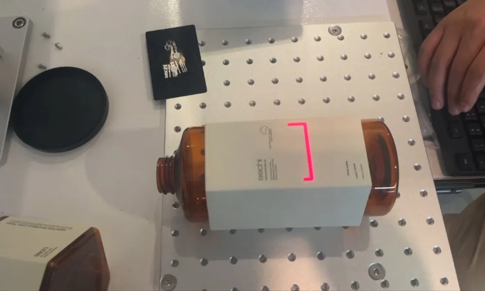
The variables can then be changed in a controlled way. The important point is not to turn the page into a universal parameter recipe. Different UV sources have different pulse characteristics, and different materials can move the relevant threshold substantially.
Instead, the test should establish relationships such as:
- increasing deposited energy improves contrast up to a point, but beyond that point surface damage begins;
- reducing scan speed improves removal, but accumulated heat or cycle time becomes unacceptable;
- changing focus alters the energy density enough that mark quality becomes sensitive to normal part-height variation.
A robust test deliberately looks for both sides of the window.
Acceptable region: the process meets the mark requirement.
Failure boundary: the process begins to produce unacceptable damage, poor readability, instability, or cycle time.
The distance between them is often more informative than the appearance of the single best sample.
What Should Be Checked Before a UV Marking Process Is Approved?
Final approval should answer three different questions.
Did the laser create the required mark? That includes contrast, dimensions, code readability, surface appearance, depth where relevant, and any customer-defined visual requirement.
Did it avoid unacceptable side effects? That includes melting, cracking, substrate damage, distortion, residue, excessive ablation, coating breakthrough, contamination, or changes that could affect function.
Can the result remain stable in production? That means checking multiple parts and realistic variation in material batch, part position, focal height, surface condition, handling, and production speed.
Durability should also match the real service environment. A mark that passes initial visual inspection may still fail after abrasion, cleaning, chemical exposure, heat, sterilization, or other application-specific conditions.
For machine-readable identification, scanability should be measured rather than judged visually.
For polymer, coating, adhesive, or film processing, fume and particle extraction should be evaluated as part of the system rather than added only after production begins.
The approval decision is therefore not simply whether the UV laser can make the mark. It is whether the UV process can repeatedly make an acceptable mark at production speed while preserving the part and remaining inside the required process and safety boundaries.
Frequently Asked Questions About UV Laser Marking
Does UV laser marking really produce no heat?
No. Cold marking is useful shorthand for a process that can reduce unwanted thermal influence in suitable applications. It should not be interpreted as zero heat. Published 355 nm polymer studies show that photochemical and photothermal mechanisms can both contribute depending on the material and processing regime. ScienceDirect: 355 nm Polyimide Processing Study
Can a UV laser mark metal?
Yes, but capability and suitability are different questions. UV can process selected metals and coated metallic surfaces, but conventional bare-metal identification and especially deep engraving often give fiber lasers a stronger production case.
Is higher UV power always better?
No. Higher available power can increase throughput when the application can use it, but it does not automatically improve feature definition or reduce damage. The correct power class should be selected after the usable material process window is understood.
Is UV always more precise than fiber?
No. The short 355 nm wavelength gives UV a fundamental focusing advantage under comparable optical conditions, but actual spot size also depends on beam quality, beam diameter, focal length, and aberration, while the final mark additionally depends on material response. Edmund Optics: Laser Beam Expander and Focus Relationships
Why can two parts made from the same plastic mark differently?
Because the nominal polymer family does not describe the full optical response. Pigment, dye, filler, carbon black, flame-retardant package, laser additive, and other formulation changes can alter absorption and therefore change the marking result. TRUMPF: Laser Marking Plastics
The main reason to choose UV laser marking is not that 355 nm is newer, colder, more precise, or more expensive.
The reason is that a shorter wavelength can change three parts of the process at the same time: how the material absorbs the beam, how tightly the energy can be delivered, and how far the desired material response can be separated from an unwanted damage mechanism.
That advantage is strongest when the application combines fine features with a narrow tolerance for thermal or structural damage. It becomes weaker when the job is primarily about deep material removal, conventional metal marking, or another process where a different wavelength already provides a wider and more productive operating window.
The final decision should follow this path: actual material → required mark → unacceptable failure → wavelength/material interaction → optical requirement → process-window validation → cycle time → production approval.
Application Review
Need to confirm whether 355 nm UV is right for your material?
Send the actual material, required mark, unacceptable failure conditions and production target for a technical review before you finalize the laser configuration.