
Material guide · Fine surface marking
Fine Laser Marking on Sapphire and Display Glass
Sapphire and display glass can be evaluated for fine laser marking, but the product name does not select the process. The useful route depends on the actual sapphire or glass grade, strengthening state, surface finish, coating or ink stack, mark location, feature size and acceptance method. A clear-looking mark can still fail if it introduces haze, edge damage, microcracks, debris or unstable code reading. This guide shows how to identify the layer being marked, screen a laser route, diagnose common failures and define a production-representative sample test before equipment selection.
Start With the Surface Stack, Not the Product Name
The first decision is not “Which laser marks a display?” It is “Which material or layer will absorb the laser energy?” A cover window described as display glass may be bare glass, chemically strengthened glass, printed on the back, coated on the front or laminated with a functional film. Sapphire is a different crystalline material again. These surfaces should not share one unqualified process recommendation.
Sapphire crystal
For sapphire, confirm the grade, thickness, polish, crystal orientation if known, marking side and the distance from edges, holes or other stress concentrators. The desired result also matters: a fine visible surface change and material removal are different process targets. A route that creates acceptable contrast may still produce roughness or local damage that is unsuitable for an optical zone.
Bare and strengthened display glass
For display glass, identify whether the sample is untreated, thermally treated or chemically strengthened. Strengthening state, thickness, edge quality and prior processing can change the risk tolerance. Finished strengthened glass deserves particular caution near edges, cutouts and thin sections because a local defect may matter even when it is difficult to see without suitable inspection.
Printed, coated and functional layers
If ink, paint, an anti-reflective layer, conductive coating, masking layer or protective film is present, the laser may interact with that layer before it reaches the glass. Record the layer location, color, thickness if available, adhesion requirement and whether partial removal is allowed. A successful coating-removal test does not prove that the underlying glass can be marked with the same settings.
Send with the sample: material designation, strengthening or heat-treatment state, total thickness, finish, coating/ink/film description, marking side, edge distance and a cross-section or layer drawing when available.
Where Are Sapphire and Display Glass Used, and Why Are They Marked?
Sapphire and display-glass parts are commonly used where a hard, transparent or optically controlled surface must also carry identification, alignment or functional information. The marking requirement depends on whether the laser is interacting with the substrate itself or with a printed or coated layer, and whether the mark sits inside or outside a functional optical area.
Display and protective cover components
Cover windows, display covers and similar protective glass parts may need part identification, serial or lot traceability, fine legends or machine-readable codes. The mark location is often constrained by visible-area boundaries, edge distance and the need to avoid haze or obvious surface damage.
Optical and sensor windows
Sapphire or glass windows used around sensors, optics or instruments may require a small identifier, orientation reference or assembly mark outside the active optical zone. Here, contrast alone is not enough: the test should also check scatter, reflection change, roughness and damage close to the functional area.
Printed and coated glass parts
Some products use back-side ink, masking, decorative print or functional coatings. The laser task may therefore be selective layer removal or local patterning rather than direct glass marking. In that case, coating chemistry, adhesion and the condition of the exposed substrate become part of the acceptance decision.
Why this matters: the same nominal material can require a very different process when the goal changes from a visible identifier to a readable code, an optical-zone reference or selective coating removal. Product context defines the acceptance criteria before laser selection begins.
What Is Usually Marked on Sapphire and Display Glass?
The content can be simple or machine-readable, but it should be defined before the laser route is compared. Specify what the mark must communicate, where it can be placed and how small the production feature must be.
Identification and traceability
Typical content includes part or model identifiers, serial numbers, lot or batch IDs and other traceability data. When the mark changes by part, confirm how the data will be supplied and whether the content must be verified after marking.
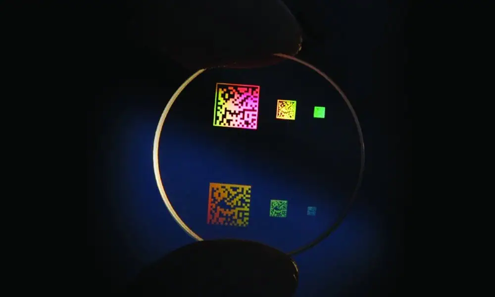
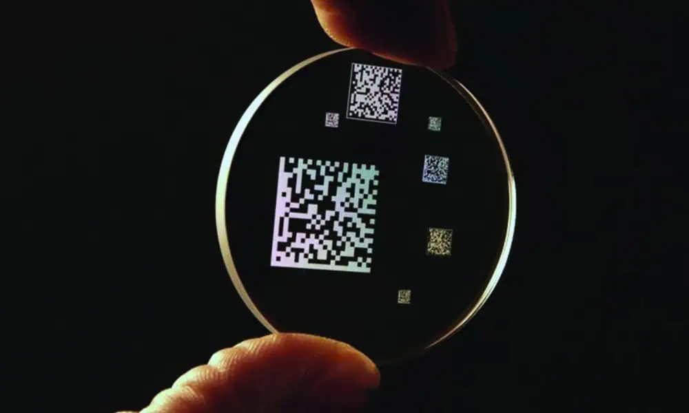
Data Matrix and QR codes
For machine-readable marks, define the code type, cell size, quiet zone, data content, reader, lighting and pass/fail method. A code that looks sharp in a close-up photograph is not automatically stable under the intended production reader.
Logos, legends and reference marks
Fine logos, product legends, orientation marks and assembly references may be required outside the active optical area. Define minimum line width, viewing direction and the permitted visual change so the process is not optimized for contrast at the expense of surface quality.
Selective coating or ink patterns
When the task is to open, remove or modify a printed or coated area, provide the exact layer stack and required geometry. The target is then controlled layer interaction, not a generic “glass mark,” and the exposed substrate must be inspected separately.
What Marking Result Do You Need?
Two parts can carry the same content but still require different processes because the acceptable surface effect is different. Convert “fine marking” into an observable result that can be inspected on the real part.
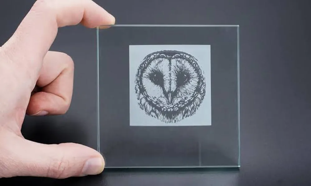
Fine visible text or graphics
Define the minimum line width, character size, contrast direction, viewing distance and permitted roughness. The mark should remain legible under the real background and lighting without creating unacceptable haze or a distracting change around the feature.
Stable machine-readable code
The target is repeatable reading, not only visual sharpness. Evaluate cell geometry, edge definition, contrast, distortion, contamination, focus tolerance and reader performance across representative parts and positions.
Controlled texture or frosting
When a visible textured or frosted surface is required, define the allowed roughness, optical appearance and affected area. Uniformity, debris, cleaning response and any crack indication should be checked instead of judging the result only by brightness or contrast.
Selective layer removal
For ink or coating removal, acceptance should include removal completeness, edge definition, residue, adhesion around the mark and the condition of the exposed substrate. A clean center with lifted edges or damaged glass is not a stable selective-removal result.
| Target result | What to specify | What to verify |
|---|---|---|
| Fine visible mark | Minimum line, viewing distance, contrast direction | Edge quality, haze, residue and legibility under real lighting |
| Machine-readable code | Code type, cell size, data source, reader setup | Readability across samples, positions and focus variation |
| Surface texture or frosting | Allowed roughness and optical appearance | Uniformity, debris, microcrack indication and cleaning response |
| Ink or coating removal | Layer identity, allowed substrate exposure, edge tolerance | Removal completeness, adhesion around the mark and substrate condition |
Which Laser Route Should Be Screened First?
Laser selection should follow the surface stack and target mechanism, not a wattage shortcut. For fine features and a lower effective heat-input direction, UV is often a practical first screening route. That is not a universal approval: spot size, pulse behavior, focus, scan strategy and material absorption still determine the outcome.
| Actual surface | Typical target | First screening direction | Main risk to check |
|---|---|---|---|
| Sapphire crystal | Fine visible mark, text or code | UV is often a practical first screen; compare another route only when sample response justifies it | Roughness, haze, local damage and edge sensitivity |
| Bare or strengthened display glass | Fine surface change outside a critical optical zone | Begin with a low-heat-input fine-feature route such as UV, then compare only if the required effect is not stable | Microcracks, chipping, haze, stress-sensitive edges and focus tolerance |
| Printed or coated glass | Selective ink/coating change or removal | Screen the wavelength that couples to the actual layer; UV, green or 1064 nm may be candidates depending on the stack | Substrate damage, residue and coating delamination |
| Glass requiring stronger frosting or surface texture | Visible textured/frosted effect | CO2 may be screened when stronger surface interaction is acceptable | Thermal shock, roughness, debris and edge risk |
UV for fine, lower-heat-input screening
A UV configuration can be worth screening when small features, limited thermal influence or selective interaction with a coating is important. The decision still depends on whether the target layer absorbs usefully, whether the process creates the required contrast and whether the surrounding glass remains acceptable. “Cold marking” should not be interpreted as zero heat or zero damage.
Green for absorption-sensitive evaluation
Green wavelengths may be evaluated when the material or functional layer responds more usefully than it does at common infrared wavelengths. This is a project-screening direction, not a default recommendation. Availability, optical configuration, target feature, layer stack and sample result must all be confirmed before a machine is specified.
CO2 for conditional glass-surface interaction
CO2 systems can interact strongly with many glass surfaces and may produce frosting or surface removal. For thin, strengthened or optically critical display glass, that stronger surface interaction can also narrow the useful window and increase thermal-shock or roughness concerns. It should be tested against the required mark scale and structural/optical acceptance rather than chosen because it is commonly associated with glass.
1064 nm for selected coatings or modified surfaces
Fiber or MOPA systems at common near-infrared wavelengths are not a universal answer for bare clear glass. They may still be relevant when an ink, coating, additive or prepared surface absorbs the wavelength and the target is layer change or removal. In that case, the approval belongs to the complete stack—not to “glass” as a broad category.
| Route | Why screen it | Main caution | Decision evidence |
|---|---|---|---|
| UV | Fine features and lower effective heat-input direction | Not heat-free; absorption and focus still control damage | Feature quality, haze/crack inspection and repeatability |
| Green | Potentially useful response for selected materials/layers | Requires confirmed system fit and sample evidence | Compare with UV or another justified route |
| CO2 | Strong surface interaction with many glasses | Thermal shock, roughness and scale may be limiting | Surface result plus structural/optical acceptance |
| 1064 nm fiber/MOPA | Selected absorbing coatings, inks or modified surfaces | Do not generalize coating response to bare glass | Layer selectivity and substrate condition |
How Do Part Shape, Thickness and Size Change the Process?
A route that works at the center of a thick coupon may fail near the edge of a thin production part. Geometry and setup therefore belong in the material decision. Mark location, flatness, clamping, focus and working distance can change both energy distribution and defect risk.
Edge distance and stress concentration
Record the distance to edges, holes, notches, cutouts and prior damage. Test the actual critical location rather than moving the mark to an easier area on the sample. If a mark near an edge produces chips or crack indications while a center mark does not, the geometry—not only the nominal material—has changed the approval decision.
Focus and flatness
Fine marks depend on a controlled spot at the surface. Part bow, thickness variation, coating-side orientation and a large field can shift the effective focus. The useful field should therefore be selected with feature size and focus tolerance in mind; a larger marking field is not automatically a better production choice.
Fixture pressure and contamination
The fixture should locate the sample without introducing local stress, scratching an optical face or blocking extraction. Dust, fingerprints, adhesive residue and protective films can change the visible result and create debris. Cleaning and handling conditions should be consistent during route comparison.
Center-to-edge consistency and access
Compare the same feature at representative positions, including the center and the most critical edge zone. Confirm whether the laser must access the front or back side and whether the final assembly changes orientation, working distance or inspection. Vision or height compensation may be relevant when position or surface height varies, but those are configuration decisions derived from the sample—not assumptions attached to the material page.
Read the Failure Mode Before Increasing Power
Low contrast does not automatically mean “add power.” More energy can deepen surface damage, widen a heat-affected zone or create debris without solving absorption or focus. Treat the visible failure as evidence about the current route, then decide what to check next.
Microcracks and chipping
Crack indications or edge chips can point to excessive local stress, an unsuitable energy-delivery strategy, a vulnerable location or pre-existing sample damage. Stop treating the result as a cosmetic defect. Recheck the material state, location, focus, fixture and wavelength direction, and use an inspection method appropriate to the risk.
Uncontrolled haze and optical distortion
If the marked area becomes cloudy or changes reflection outside the intended boundary, compare heat input, hatch/scan strategy, focus and the actual target mechanism. In an optical zone, even a readable mark may be unacceptable when it creates visible scatter or changes the appearance of the finished assembly.
Residue, recast and coating delamination
Residue may come from the substrate, an organic coating, ink or contamination. Confirm the layer stack before changing settings. For layer removal, inspect the remaining edge and adhesion around the mark; a clean center with lifted edges is not a stable selective-removal result.
Weak code edges
Poor reader performance can result from insufficient contrast, oversized or rounded cells, debris, distortion, lighting or focus variation. Compare code results with the production reader and lighting before changing the laser route. The goal is a repeatable reading condition, not only an attractive enlarged image.
| Observed symptom | Check next | Decision direction |
|---|---|---|
| Chip or crack indication | Edge distance, pre-damage, focus, fixture stress and energy distribution | Reduce risk, relocate only if the drawing permits, or screen another route |
| Haze outside the mark | Heat input, focus, hatch, passes and material/layer identity | Narrow the interaction or reject for an optical zone |
| Residue or lifted coating | Layer chemistry, cleaning, adhesion and removal selectivity | Refine layer-removal strategy and inspect substrate |
| Unstable code reading | Cell geometry, contrast, lighting, reader angle and focus variation | Correct the optical/read setup or change the mark route |
A Good Sample Is More Than One Clear Photograph
Equipment approval should be based on production-representative samples and an agreed inspection method. One clear photograph cannot show hidden crack risk, batch response, focus tolerance, coating adhesion or reader stability. The test plan should reproduce the material, geometry, mark position and viewing conditions that matter in production.
Sample matrix
Provide multiple samples from the real material stack, including relevant lots or suppliers when variation is expected. Include the critical center and edge positions, both marking sides if applicable, and any coating or strengthening variations that may be supplied in production.
Inspection and reader setup
Define visual lighting, magnification or crack-inspection method, background, reader model and angle before comparing routes. For a machine-readable code, save the data content and grading or pass/fail rule. For an optical mark, define acceptable haze, reflection change, surface texture and contamination.
Batch, position and focus checks
Compare repeated marks across samples and positions, and introduce realistic focus or placement variation when the production fixture cannot hold a single ideal condition. A narrow but stable window may justify tighter fixturing or height control; an unstable window may justify another wavelength or marking mechanism.
Cleaning, wear and environment
If the finished mark will be cleaned, rubbed, bonded, laminated, heated or exposed to a defined environment, include the relevant check in the acceptance plan. The test should reflect the real requirement without inventing a generic “permanent” claim. Record rejection examples so the supplier and buyer judge the same boundary.
- Exact material, strengthening state and layer stack are represented.
- Mark content, feature size, side and critical edge location match the drawing.
- Visual, structural and reader acceptance are separate and measurable.
- Multiple samples, positions and relevant variations are included.
- Cleaning, handling and environment checks reflect the finished use.
- A rejection rule is agreed before equipment approval.
What Should a Useful Sample Report Show?
A useful sample report should make it possible to judge the exact material stack, the mark mechanism and the failure boundary—not just show a close-up of a successful-looking mark. This is especially important when comparing direct substrate marking with coating or ink removal.
Identify the exact sample
Record sapphire or glass type, strengthening state, thickness, marking side, coating/ink stack, supplier or lot when relevant, and the critical mark location. A result without this context cannot be safely transferred to a different display-glass or sapphire construction.
Show the result at useful scale
Use an overall part view to show position and edge distance, plus a close view for feature quality. For codes, include the production reader result. For coating removal, show both the cleared area and the remaining layer edge.
Inspect the risk zone
Document haze, chips, crack indications, roughness, residue, delamination and the condition of the optical or functional area around the mark. When strength is a product requirement, the customer-defined validation method should be treated separately from visual inspection.
Show repeatability, not one best part
Compare multiple parts, positions and relevant lots or process variations. The evidence set should make clear whether the same route remains acceptable at the center, near critical edges and across the realistic focus and placement range.
Evidence rule: direct sapphire/glass marking and coating removal should be identified separately. Real sample photographs and inspection records should only be used as result evidence when the material and test context are known.
From Sample Review to Machine Configuration
Once a sample route is technically credible, the machine should be configured around the accepted process and the real handling method. A small, flat, manually loaded mark may fit a standard enclosed or benchtop direction. Variable position, multiple nests, surface-height changes, automatic data, inspection or line handling require a broader project review.
Material and sample inputs
Send the exact samples, material designation, strengthening state, coating or ink information, total thickness and any handling restrictions. If several approved suppliers or lots will be used, include them rather than testing only the easiest sample.
Mark drawing and acceptance
Provide the mark file, dimensions, minimum feature, location, side, edge distance, visual target, code/reader method and rejection criteria. Separate must-have requirements from preferences so the route comparison does not optimize one cosmetic detail at the expense of structural or reading acceptance.
Production geometry and volume
Describe part dimensions, orientation, loading, fixture constraints, position variation, planned output and the full cycle—not only the laser scan. Loading, positioning, marking, verification, data handling and unloading all contribute to production capacity.
Configuration review
Zhuorui Laser can review the application, compare a suitable laser direction, match the source, optics, controls and machine structure, and assess fixture, enclosure, extraction, vision or motion needs. For printed, coated or laminated surfaces, that review should include the available layer chemistry or safety data and an extraction/filter plan for the expected plume. More complex integration remains conditional on the sample, layout, interfaces, safety review and confirmed configuration.
For a defined standard-machine requirement, send the material stack, mark drawing and acceptance criteria with your RFQ. If the project includes vision, multiple positions, motion, automated handling or data integration, use the custom-project path so those dependencies can be reviewed together.
Questions Engineers Ask Before Testing
Can a UV laser mark sapphire?
UV is a reasonable screening direction for fine surface work on selected sapphire samples, but the acceptable result depends on grade, polish, thickness, geometry, target mechanism and inspection. It should not be treated as a universal crack-free or haze-free guarantee.
Is CO2 suitable for display glass?
CO2 can create strong surface interaction on many glasses, including frosting or removal. On thin, strengthened or optically critical display glass, that interaction may be too aggressive or narrow the usable window. Test it only against the exact material, feature size and structural/optical acceptance.
Can a fiber or MOPA laser mark clear glass?
Common near-infrared fiber/MOPA systems are not a universal route for bare clear glass. They may be relevant when a coating, ink, additive or prepared surface absorbs effectively. Approve the complete stack, not the broad material name.
How should microcracks be checked?
The method should reflect the risk and the finished part. At minimum, define suitable magnification and lighting, inspect critical edges and compare multiple samples and positions. Higher-consequence products may require a customer-defined inspection or strength-validation method beyond a visual page guide.
Does chemically strengthened glass need a different test?
Yes. The strengthening state, edge condition, cutouts, mark location and prior processing should be represented in the test. A coupon or unstrengthened blank may not reproduce the response or risk of the finished display glass.
Does Zhuorui provide subsurface crystal engraving?
This page and the current Zhuorui scope address controlled external-surface marking and layer interaction. Internal or subsurface crystal engraving is not presented here as an available production offer.