
Tempered Glass Laser Marking
Tempered glass can be evaluated for laser marking, but the first decision is whether the mark should be made before tempering, after tempering, or on a coating or print layer. Finished tempered glass carries residual stress, so crack risk, edge and hole location, fixture pressure, strength retention and final product approval matter more than the laser source name alone.
Request a Tempered Glass Sample Review Discuss Marking RiskTempered Glass Can Be Evaluated for Laser Marking, but Post-Tempering Marks Need a Stricter Qualification Gate
A finished tempered panel is not equivalent to an untreated glass coupon. Local heating, surface damage or a new stress concentration can cause immediate breakage or leave a part that looks acceptable but no longer meets the product owner’s strength, safety or durability requirement.
First question: can the mark be incorporated before tempering?
If the glass process and final appearance allow it, a pre-temper route is usually worth evaluating before direct modification of the finished tempered surface. The same part should then be inspected after tempering for appearance, distortion and downstream compatibility.
Post-temper marking is conditional
Finished tempered glass should be reviewed using the actual part condition, mark location, thickness, edge and hole geometry, coating stack, fixture method and acceptance criteria.
The real target may be a surface layer
Paint, ceramic frit, low-E layers, printed decoration, films and back coatings can change absorption and may allow a process that acts mainly on the layer rather than the glass body.
Confirm What Glass Condition You Are Actually Marking
The words “glass” or even “safety glass” are not enough for machine selection. Confirm the strengthening route and final surface stack first, because a pre-temper blank, a fully tempered finished panel and a coated panel do not represent the same laser task.
Keep the material category precise: untreated or annealed glass belongs in the general glass marking guide. Borosilicate compositions belong in the borosilicate glass guide. Chemically strengthened cover glass should be treated as a separate specialty-glass qualification unless its exact process is confirmed.
Tempering state
Confirm whether the part is not yet tempered, fully thermally tempered, heat-strengthened, or another strengthened-glass condition. Do not transfer approval between these states without re-testing.
Surface stack
Identify paint, frit, low-E coating, printed ink, anti-fingerprint layer, film, adhesive or back coating before deciding whether the laser is intended to modify the glass or only a surface layer.
Thickness and color
Record the actual thickness and glass appearance used in production. They affect focus setup, handling, visual contrast and whether a previous sample is representative.
Existing condition
Chips, scratches, edge damage, drilled features and prior processing can change the starting risk. Test pieces should represent the condition that will actually enter production.
Common Tempered-Glass Products That Need Identification or Functional Marks
The application context matters because the acceptable mark depends on what the panel must still do after marking. The examples below stay focused on products where the tempered condition itself affects the marking decision.
Appliance and control panels
Oven doors, cooktop covers and control glass may need branding, icons, legends or production IDs while still meeting appearance, cleaning and heat-exposure requirements.
Architectural and shower safety glass
Logos, batch identification and selected decorative marks may be requested, but edge location, installation loads, cleaning and safety-glazing approval remain part of the decision.
Selected thermally tempered transport glazing
Where the component is confirmed as thermally tempered glass, side or component glazing can involve curved geometry, coatings, identification marks and product-specific approval. The actual glazing specification must be confirmed before direct post-temper work.
Glass processor traceability
Batch IDs, serials or process codes can support manufacturing traceability. The processor should decide whether the safer route is pre-temper marking, coating-layer marking or another identification method.
What Is Usually Marked on Tempered Glass?
The content itself changes how much area is processed, how dense the scan is and what acceptance method is needed. A small serial number is a different risk and production task from a filled logo or a large decorative field.
Branding and functional legends
Logos, icons, control legends and selected decorative elements where appearance and cleaning resistance matter.
Serial and batch identification
Human-readable serials, lot numbers, date codes and internal production IDs for traceability.
QR or Data Matrix codes
Machine-readable codes that require both code quality and an acceptable glass condition after marking.
Coating or print-layer patterns
Selective removal or modification of paint, print, frit or other surface layers when the layer—not the glass body—is the intended laser target.
Important: if a mark is intended to serve as a regulatory, certification or safety-glazing identification mark, do not assume that laser marking is automatically accepted. The product owner and applicable approval route must define what marking method and evidence are acceptable.
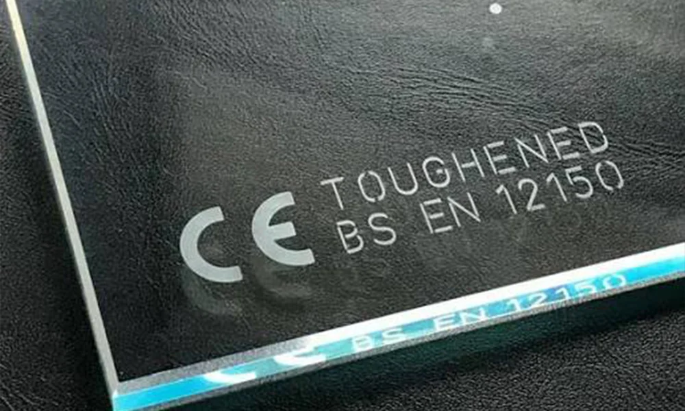
Example: Permanent Identification on Toughened Glass
This example shows the type of permanent identification that may appear near the edge of a toughened-glass panel. Use it to understand mark content and placement—not as proof that the same post-temper process is approved for another glass product.
Final approval still depends on when the mark is made, the actual glass condition, and the required post-mark qualification.
Define the Result Before Comparing Laser Sources
“Can it mark?” is too broad. The practical route depends on whether you need a fine visible mark, a readable code, a frosted appearance, coating removal or a deeper surface effect.
| Desired result | What to evaluate | Tempered-glass boundary |
|---|---|---|
| Fine visible logo or text | Line quality, contrast, haze, viewing angle and surface condition. | Prefer the shallowest practical effect and validate the real tempered part. |
| QR / Data Matrix | Cell definition, contrast, reader setup, mark area and repeatability. | A readable code does not by itself prove the glass remains acceptable. |
| Frosted or matte appearance | Uniformity, roughness, optical appearance and cleaning response. | Inspect for surface damage and strength implications, not only cosmetic quality. |
| Coating or print removal | Layer selectivity, exposed-glass appearance, adhesion around the mark and fumes. | Confirm that the laser is acting mainly on the intended layer and does not damage required coating function. |
| Deep engraving | Depth, roughness and material removal. | Not a default target for finished tempered glass. If depth is required, the process should be reconsidered at the pre-temper or product-design stage. |
Thickness, Panel Size, Curvature and Edge Features Change the Test
A flat coupon is only useful when it represents the real production part. Tempered-glass qualification should include the actual geometry and support condition because the same mark can behave differently near stressed features or under different fixture loads.
Thickness
Do not assume a process approved on one thickness transfers directly to another. Thickness affects handling, focus setup and how representative a thermal or surface-damage test is.
Large panel size
Large panels add support, flatness, loading and mark-position issues. Machine selection may depend on workstation access or motion, not only the nominal marking field.
Curved glass
Curvature changes focus and working distance and can make fixture support more critical. Validate the real surface height and mark location instead of copying a flat-panel recipe.
Edges, holes and notches
Marks close to edges, drilled holes, notches or hardware cutouts require extra caution because these features already influence local stress and handling loads.
Existing chips or scratches
A damaged sample can fail for reasons unrelated to the new mark, while a pristine coupon can hide production risk. Record the incoming part condition during trials.
Fixture pressure and support
Clamp force, point contact, unsupported areas and hardware references can change the mechanical condition during marking. The production fixture should be part of final validation.
Choose the Process Route Before You Choose the Laser Source
For tempered glass, the first decision is where in the glass-processing sequence the mark belongs. Only after that route is accepted should UV, CO2 or another laser source be compared.
Mark before tempering
Test first when the mark can be built into the glass-processing sequence.
Qualification question: Does the mark remain acceptable after tempering and downstream processing?
Direct post-temper marking
Use only when a finished panel must be marked and a real-part qualification trial is permitted.
Qualification question: Can the required mark be produced without unacceptable fracture, damage, strength or approval risk?
Process the coating or print layer
Use when contrast comes from removing or modifying paint, print, frit, film or another surface layer.
Qualification question: Can the layer be processed selectively while preserving required glass and coating performance?
Use external or non-laser identification
Use when direct modification of the finished tempered surface cannot be accepted or qualified.
Qualification question: Can another identification method satisfy traceability and service-life requirements?
| Laser route | Reason to screen it | Boundary |
|---|---|---|
| UV laser | Often worth screening for fine, localized surface marks and code detail. | Do not equate UV with automatic safety; the real part and process window still require qualification. |
| CO2 laser | Can be screened when a glass-surface frosting or matte effect is requested. | Thermal and surface-damage risk must be reviewed carefully on finished tempered glass; aggressive engraving is not a default route. |
| Fiber / MOPA fiber | Relevant mainly when a coating, pigment, film, metallized layer or other responsive surface material is the real target. | Not the normal first route for bare clear glass body marking. |
| Green laser | Project-specific screening when a validated configuration and sample evidence support it. | Do not treat it as a default tempered-glass recommendation without actual project evidence. |
A Clean-Looking Mark Can Still Be an Unacceptable Tempered-Glass Result
The main failure question is not only whether the laser can create contrast. It is whether the finished part remains acceptable after marking, handling, cleaning, installation and service.
Immediate fracture
The panel cracks or releases during marking because the local process or existing defect interacts with the tempered stress state.
Microcracks or surface flaws
The mark appears visually acceptable but creates localized damage that may require closer inspection or additional qualification.
Reduced strength after marking
Visual inspection alone may not establish that a strength-sensitive or safety-related part still meets its required performance.
Edge, hole or notch sensitivity
A mark too close to an existing stress-sensitive feature can be less acceptable than the same mark in a lower-risk location.
Fixture-induced damage
Excess clamp pressure, point loading or poor support can contribute to failure during or after marking and should be part of the trial record.
Coating or optical failure
The part may pass a crack check but still fail because of coating lift, haze, poor contrast, unwanted reflection, cleaning damage or loss of coating function.
Laser safety still applies: enclosure, interlocks, beam containment, wavelength-appropriate protection and fume extraction must be reviewed for the complete machine. For this material page, however, the product-specific glass integrity gate remains the primary qualification issue.
Validate the Real Tempered Part, Then Get the Required Glass-Process Approval
A reliable recommendation needs the final material condition and a defined acceptance method. A successful mark on a coupon is not enough when the production panel has different tempering, thickness, coating, curvature, edge features or fixture loads.
What to send for a useful trial
- Tempering status: not yet tempered, fully thermally tempered, heat-strengthened or another confirmed strengthened condition.
- Glass details: thickness, color, coating, print, film, ceramic frit, low-E layer or back paint.
- Drawing: mark location, edge distance, holes, notches, curved area, hardware positions and fixture references.
- Mark target: logo, QR/Data Matrix, serial number, functional legend, coating removal, frosting or another defined effect.
- Acceptance: visual limits, code readability, cleaning, abrasion, heat exposure, integrity requirements and reject definition.
- Production: parts per hour or cycle target, loading method, workstation access, extraction, enclosure and automation needs.
Mark the real condition
Use representative glass, geometry, surface stack, mark location and fixture support. Record any existing chips, scratches or visible defects before testing.
Inspect more than appearance
Check contrast and readability, then inspect for cracks, chips, roughness, haze, coating lift and other damage around the marked area.
Confirm processor and product approval
Before direct post-temper marking moves into production, confirm whether the glass fabricator, processor, product owner or applicable project requirement permits modification of the finished tempered surface.
Post-mark strength or integrity evaluation
When glass strength, safety performance or structural use is part of the product requirement, visual inspection alone may not be sufficient. The glass processor, product owner or applicable standard should define whether strength, stress, breakage, impact, bending or other qualification testing is required for that product.
When to stop and re-test
Re-test when the glass supplier or processor changes, tempering route changes, thickness or coating changes, the mark moves closer to an edge or hole, geometry or curvature changes, fixture support changes, mark size or fill density changes, service conditions change, or the laser/optics/focus strategy is materially changed.
Turn the Approved Test Route Into a Practical Machine Configuration
Machine selection should follow the validated marking route. The information below tells Zhuorui what must be configured around the actual glass part instead of quoting a machine from the material name alone.
| Project input | What it influences |
|---|---|
| Tempering state, surface stack and target effect | Whether the project should use pre-temper marking, direct post-temper marking, coating-layer processing or another identification method, then which laser source should be screened. |
| Mark size, detail and code requirement | Optics, marking field, focal setup and whether code verification needs to be included in the acceptance process. |
| Thickness, curvature and height variation | Focus method, working distance, positioning approach and whether additional motion or height compensation needs evaluation. |
| Edges, holes, notches and support points | Fixture strategy, safe mark location, clamping method and production handling. |
| Large-panel dimensions | Workstation access, support structure, motion requirements and whether the part or laser head must move. |
| Parts per hour and loading method | Overall cycle design, operator loading, fixture count, automation level and how marking time fits into the full production cycle. |
| Coating chemistry and by-products | Extraction or filtration review and whether additional process controls are needed. |
| Machine safety requirement | Enclosure, interlocks, beam containment and the complete machine safety review. |
For a quote: send the actual or representative part, drawing, mark artwork, target result, tempering status, coating information, expected parts per hour, loading method and required acceptance checks. These inputs are what turn a sample result into a realistic machine configuration.
Tempered Glass Laser Marking FAQs
Can tempered glass be laser marked after tempering?
It can be evaluated, but it should not be treated as a universal yes. Direct post-temper marking needs the real finished part, crack and surface-damage inspection, geometry review and approval against the final product requirement.
Is it better to mark glass before tempering?
When the design allows it, pre-temper marking is usually the first route to evaluate because the mark can be included before the final residual-stress state is created. The same part should still be checked after tempering for appearance and downstream compatibility.
Is UV safer than CO2 for tempered glass?
Not automatically. UV is often worth screening for fine localized marks, while CO2 can suit selected surface-frosting effects, but wavelength alone does not determine crack or strength risk. The actual process window and finished part still need qualification.
Can a fiber laser mark tempered glass?
Fiber or MOPA fiber is generally not the first route for bare clear glass. It may be relevant when the real target is a coating, pigment, printed layer, metallized film or another responsive surface material.
Can Zhuorui quote a machine from a photo only?
A photo can start the review, but a useful machine direction needs the tempering state, thickness, coating, drawing, mark size and location, target effect, parts-per-hour goal, fixture method and sample acceptance requirements.
When should the process be re-tested?
Re-test after a meaningful change to the glass supplier or tempering route, thickness, coating, geometry, edge or hole relationship, fixture support, mark density, service requirement, laser source, optics or focus strategy.
Send the Real Tempered Glass Condition Before Choosing the Machine Route
Include the tempering status, glass thickness, coating or print layer, part drawing, mark location, edge and hole relationship, target effect, required acceptance checks, parts-per-hour target and loading method. Zhuorui Laser can then review the practical process route, sample-test plan and machine configuration for your part.
Request a Quote OEM & Custom Inquiry Contact Us