
Alumina Ceramic Laser Marking
Evaluate fine codes, identification marks and controlled surface ablation on the actual alumina grade—not on the material name alone. Purity, additives, color, fired condition, finish and surface layers can all change contrast, edge quality and damage risk.
Alumina Can Be Marked, but the Process Window Belongs to the Exact Part
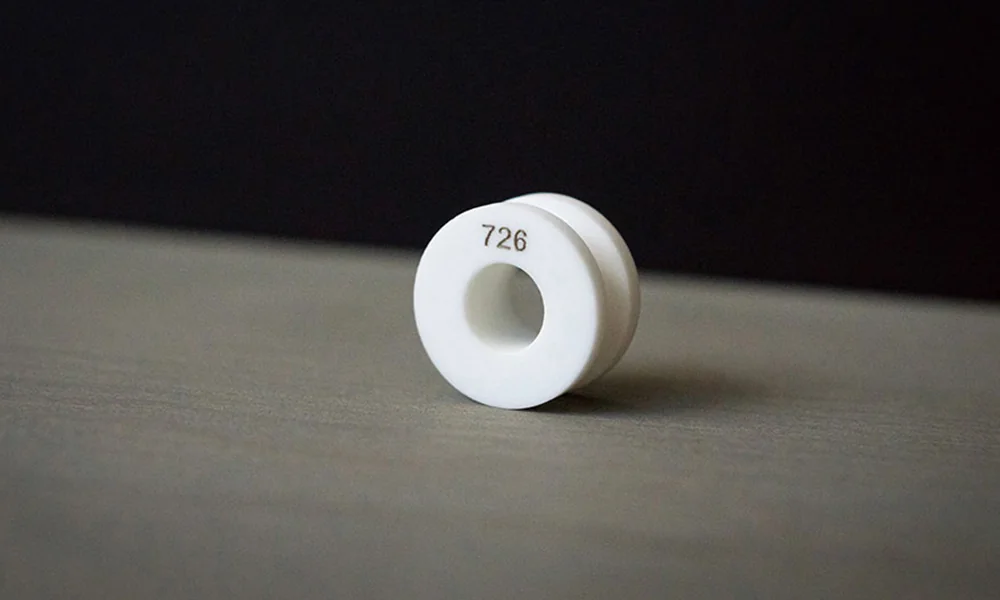
Laser marking can produce a visible change, shallow texture or controlled material removal on selected alumina ceramics. The stable result depends on the ceramic formulation and surface condition, so UV, fiber/infrared, green and CO2 systems should begin as test hypotheses rather than universal prescriptions.
For fine Data Matrix, QR, serial or alignment marks, approval must include code geometry, lighting and reader verification. For ablation, approval must also cover depth or texture, debris, edge integrity and any functional limit imposed by the component.
Return to the glass, crystal and ceramics material guide for broader brittle-material routing.
Separate Material Response from Production-System Requirements
Alumina grade, surface condition and the required mark determine whether a process is technically suitable. Production volume, part handling, code verification, automation and industry-specific acceptance determine how that proven process should be implemented in a machine.
First confirm what happens on the alumina part
- Grade, purity, additives, color and fired condition
- Polished, lapped, glazed, coated or metallized surfaces
- Contrast change, micro-ablation and layer-removal feasibility
- Chipping, microcrack, roughness and edge-risk checks
- Laser-route comparison and sample validation on the actual material state
Then define what the machine must repeat in production
- Component function and traceability requirement
- Line speed, part presentation, automation and fixture flow
- Reader integration, data connection and reject handling
- Industry validation, compliance and documentation requirements
- Production acceptance criteria beyond the material response alone
When metallization or electronics become the main target
If the key question is how the alumina body or its surface responds to the laser, evaluate the material first. If the critical target is a conductor, metallization, solder mask, circuit stack or package structure, the test must also account for that layer’s electrical, bonding and production requirements.
“Alumina” Is Not a Complete Laser Test Specification
Two parts sold as alumina can respond differently because formulation, density, finish and surface layers alter absorption, heat flow and the visible mark mechanism.
Grade and composition
Record the stated alumina grade or purity and any known sintering aids, pigments or marking additives. Do not transfer approval between formulations without comparison samples.
Color and fired state
White, black and colored bodies may not produce the same contrast. Fired density, porosity and batch condition can also change texture and debris behavior.
Surface finish
As-fired, ground, lapped and polished surfaces need separate approval because roughness, gloss and pre-existing defects affect appearance and inspection.
Layers and metallization
Glaze, ink, coating, thin film or metallized regions may become the real laser target. Define whether the process changes the layer, the interface or the ceramic body.
Geometry and edges
Thickness, curvature, holes, steps, unsupported spans and distance from an edge can change focus stability, fixturing and fracture risk.
Final part condition
Cleaned, brazed, bonded, assembled or coated parts should be tested in the condition that will enter production and inspection.
Alumina-specific state matrix
Use this matrix only as a test-planning distinction; it is not a substitute for a confirmed sample result.
| State variable | Possible process effect | Primary validation |
|---|---|---|
| Purity, grade and sintering aids | May change absorption, thermal response and contrast mechanism between otherwise similar parts. | Side-by-side code or texture result on identified grades; inspect edge and debris. |
| White, black or pigmented body | Visible contrast may come from a body change, additive response or limited ablation; color alone does not predict a dark mark. | Contrast measurement, reader test and post-cleaning appearance. |
| Dense, porous or differently fired body | Can change heat flow, roughness, particulate release and local fracture sensitivity. | Surface inspection plus functional or strength checks where relevant. |
| As-fired, ground, lapped or polished finish | Changes gloss, scattering, focus sensitivity and defect visibility at the mark edge. | Inspect edge definition under production lighting and after handling/cleaning. |
| Glazed, coated or metallized surface | The layer, interface or ceramic may be the actual target; adjacent tracks can be functionally sensitive. | Layer selectivity, residue, adhesion/electrical function and ceramic protection. |
Alumina Parts Are Usually Marked for Identification, Traceability and Assembly Control
The reason for marking matters because a simple human-readable ID, a compact machine-readable code and a controlled surface-removal task do not need the same feature size, contrast, inspection method or process window.
Electronic substrates and insulating components
Part numbers, lot IDs, orientation marks and machine-readable codes may be used to keep ceramic parts traceable through assembly and inspection. The mark must not create unacceptable damage to the ceramic body or nearby metallized features.
Precision technical ceramic components
Serial numbers, batch identification, inspection references and assembly marks help distinguish similar parts and maintain traceability after grinding, cleaning or handling. Edge integrity and crack risk can be more important than maximum contrast.
Coated, glazed or metallized alumina parts
The marking task may target the surface layer rather than the alumina body itself. In that case, the key question becomes selective layer modification or removal without unacceptable residue, ceramic exposure or functional damage.
What is usually marked on alumina?
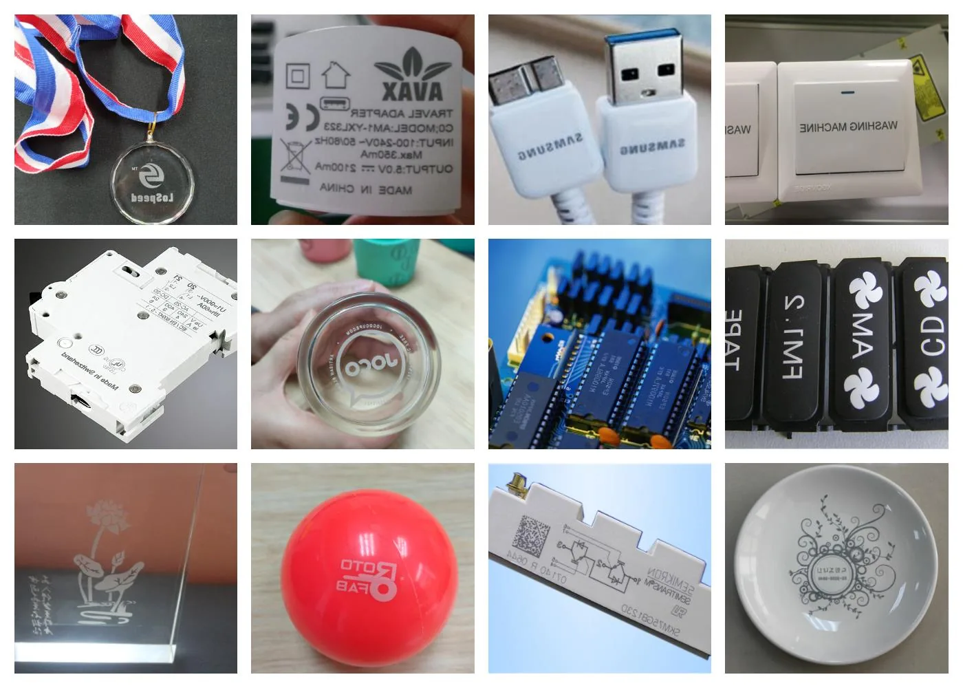
Common requests include part numbers, serial numbers, batch or lot IDs, logos, short text, symbols, orientation or alignment references, Data Matrix codes and QR codes where the available mark area and reading method support them. The content should be defined before laser trials because code density, smallest feature size and required inspection method directly affect the test route.
Define the Required Change Before Choosing the Laser
“Mark the alumina” can mean three different production tasks. Each needs its own acceptance language.
Visible contrast change
A selected formulation may show a darker, lighter or otherwise visible change with limited material removal. Confirm color, uniformity, gloss, code readability and post-cleaning stability.
Micro-ablation or engraving
Shallow texture or material removal can create tactile or optical contrast, but it raises debris, roughness, chipping, microcrack and strength questions. Depth must be measured when it matters.
Layer or coating removal
Selective removal can expose the ceramic or another layer. Verify selectivity, residue, ceramic protection, electrical or bonding function, and the condition of adjacent metallization.
Define What a Good Alumina Mark Must Achieve Before Optimizing the Process
The required result should be stated as an acceptance target, not only as “dark,” “clear” or “engraved.” A production-ready mark needs the right visual or machine-readable result without creating damage that matters to the part.
Readable identification
For text, logos and symbols, define the minimum acceptable contrast, edge clarity and visual consistency under the lighting used in production or final inspection.
Machine-readable codes
For Data Matrix or QR marks, define code size, cell size, lighting, reader or verifier method and the required read or grading criterion. A visible code is not automatically a reliable production code.
Minimal ceramic damage
Set limits for chips, microcracks, roughness, debris and heat-affected texture where these can affect strength, insulation, bonding, sealing, cleanliness or appearance.
Controlled depth or texture
If material removal is required, define the acceptable depth, profile and surface texture instead of judging the mark only from a photograph.
Stable post-process appearance
Check the result after the cleaning, abrasion, thermal exposure or other downstream steps that the part will actually experience.
Functional integrity retained
Where relevant, the mark must stay within limits for electrical insulation, metallization, bonding, strength, vacuum, wear or other part-specific functions.
Use Laser Types as Test Routes, Not Automatic Answers
Wavelength, pulse behavior, beam quality, spot size, focus control and the part itself act together. The table below is a screening framework, not a parameter recommendation.
| Route | Why it may enter a test | Main cautions | Release evidence |
|---|---|---|---|
| UV laser | Fine-feature trials, selected contrast or surface-change tasks, and applications seeking controlled energy placement. | Not automatically “cold”; repeated passes or tight focus can still create roughness, debris or damage. | Code grade, edge definition, surface inspection, cleaning and durability on the exact part. |
| Fiber / infrared laser | Selected formulations, pigmented bodies, marked additives, metallized regions or contrast/ablation trials where the actual response supports it. | White alumina does not guarantee a stable dark mark; thermal accumulation and roughness must be checked. | Contrast mechanism, heat/texture effect, reader result and functional inspection. |
| Green laser | A comparison route when absorption, fine-feature behavior or a specific layer makes it technically relevant. | Equipment scope and real sample response must be confirmed; wavelength alone does not predict approval. | Direct side-by-side sample evidence against other feasible routes. |
| CO2 laser | Selected surface-heating, texture, larger-mark or coating-removal evaluations. | Fine-code resolution, thermal loading, chipping and microcrack risk can limit suitability. | Texture/depth, edge quality, crack inspection and part-function checks. |
Which route should you test first?
Use the required mark and the actual surface stack to set the first comparison. For very fine codes or small features, UV should usually be included early because controlled energy placement and fine-feature capability are often important. For pigmented or additive-responsive alumina, or where an infrared-responsive layer is involved, fiber/infrared may deserve an early comparison. For coated or metallized parts, choose the first route around the layer that must be changed rather than around the word “alumina.” Green can be a comparison route when absorption or fine-feature behavior justifies it, while CO2 is more commonly a screening option for selected thermal-texture, larger-mark or removal tasks where heat and crack risk can be accepted and verified.
If the formulation is unknown—especially on white alumina—do not assume a dark result from fiber or any other source. Run a small, controlled comparison and select the route that meets contrast, code quality, damage and cleaning criteria on the real part.
No universal parameter table
Power, pulse settings, speed, frequency, hatch, focus offset and pass count should be developed from a controlled matrix on production-representative parts. Publishing unverified numbers would imply transferability that has not been demonstrated.
A Visible Symbol Is Not Yet a Production-Approved Code
For Data Matrix, QR, microtext and serial marks, specify the information density and the inspection setup before optimizing appearance.
Reader vs verifier: a reader confirms that a code can be decoded; a verifier evaluates symbol quality against the specified grading method. They are not interchangeable.
- Define code size, cell size, content and required grading or read criterion.
- Inspect cell growth, missing cells, edge rounding, debris and local contrast variation.
- Test under the actual illumination, angle, camera and reader configuration.
- Repeat after cleaning, abrasion, thermal exposure or process steps relevant to the part.
- Measure process consistency across positions, batches and fixture loading—not only the best sample.
Inspect Beyond Contrast
Brittle ceramic damage and functional changes may be missed by a quick photograph. Release criteria should match the risk of the finished component.
Microcracks and chips
Check mark edges, nearby holes, thin walls and unsupported areas. Use magnification or another defined inspection method when normal viewing is insufficient.
Roughness and debris
Assess loose particles, recast, porous texture and cleaning response. A high-contrast mark can still fail cleanliness, sealing, bonding or handling needs.
Depth and geometry drift
For ablation, measure depth or profile when it affects wall thickness, flatness, fit, insulation distance or another functional boundary.
Color inconsistency
Compare parts across lots and positions. Pigments, additives, finish and thermal accumulation can change the perceived result.
Layer damage
On coated or metallized parts, inspect adjacent tracks, adhesion, exposed ceramic and residue. A cosmetic result does not confirm electrical or bonding integrity.
Part-function risk
Strength, insulation, vacuum, fluid, wear, thermal or cleanliness requirements belong in the validation plan when relevant; this page does not certify them.
Build the Test Around the Final Part and Its Acceptance Method
A useful test request identifies both the material and the production decision. Substitute coupons can screen a route, but they should not release the final process.
| Input | What to provide | Why it matters |
|---|---|---|
| Material identity | Grade/purity, supplier reference, color, additives if known, fired condition and lot information | Separates formulations that may not share a process window. |
| Surface stack | As-fired, ground, lapped, polished, glazed, coated, inked or metallized; include layer purpose | Defines the actual absorption and removal target. |
| Part geometry | Drawing, thickness, curvature, holes, steps, edges, mark area, datum and fixture limits | Controls focus, support and local fracture risk. |
| Mark target | Artwork or code content, size, cell size, contrast/texture/depth target and allowable zone | Turns “make a mark” into a measurable result. |
| Inspection | Reader and verifier method, lighting, code criterion, magnification, roughness/depth method and defect limits | Defines acceptance beyond a visual photo. |
| Durability/function | Cleaning, abrasion, heat, chemicals, adhesion, insulation, strength or other relevant checks | Prevents approval of a mark that compromises the part. |
| Production | Volume, cycle target, loading method, automation, traceability data and reject strategy | Routes the job to the correct application and system configuration. |
Use the Approved Sample Result to Define the Final Machine Configuration
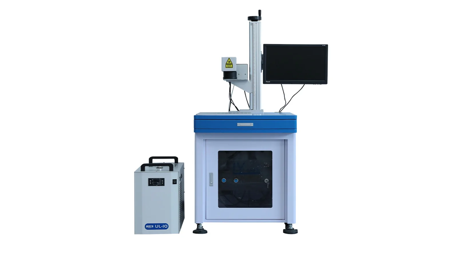
The sample test should not end with “this laser can mark alumina.” It should identify the laser route, optics, focus strategy, fixture, safety and production features required to repeat the approved result on real parts.
Laser source
Select the source route that passed the real-part comparison. Do not choose only from the material name; use the actual contrast, code, ablation and damage result.
Lens and marking field
Match field size, feature size and usable working area to the part and mark. A larger field may reduce fine-feature margin, so optics must be selected around the real artwork and tolerance.
Focus and Z strategy
Flat parts may need only a fixed, repeatable working distance. Curved, stepped or height-varying parts may require controlled Z positioning, height compensation or a different optical strategy.
Fixture and part support
Use low-stress support with repeatable datums. Small or brittle components should not be clamped through point loads near edges, holes or the mark area.
Vision and code verification
Add vision when part position or orientation varies enough to affect placement. Add reader or verifier integration when code acceptance is part of the production requirement.
Extraction, enclosure and handling
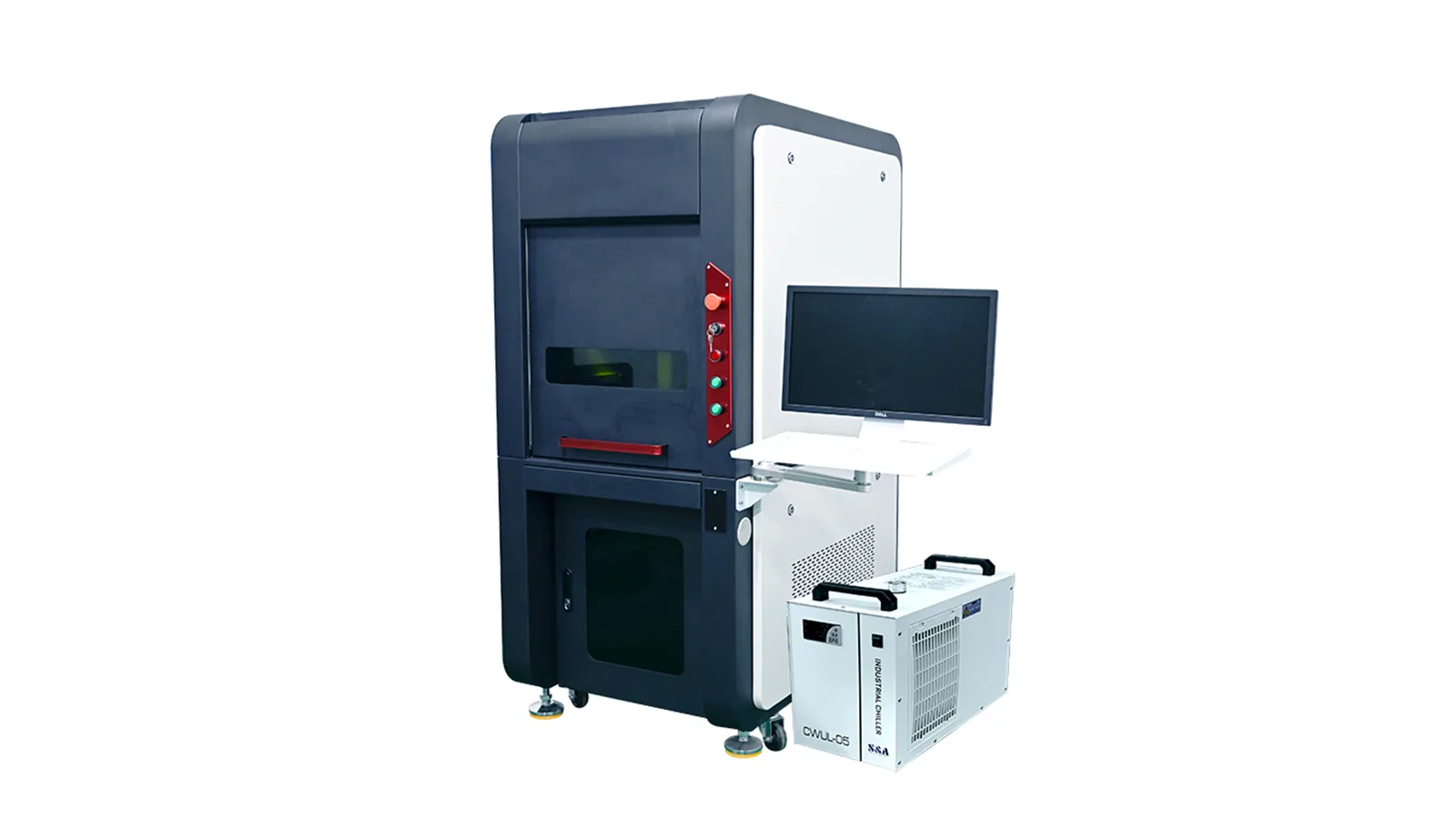
Configure extraction around ceramic particulate or removed surface layers, and review enclosure, interlocks and handling around the complete system rather than the laser source alone.
What determines the final quote?
For a useful machine quotation, provide the alumina grade or purity, surface condition, part drawing and dimensions, mark location, artwork or code, smallest feature, required contrast or depth, defect limits, reader or inspection method, target cycle time or parts per hour, loading method, fixture constraints, expected volume, and any vision, automation, data or safety requirements. These inputs determine whether the final system is a standard machine, a configured machine with fixture or vision, or a project that needs additional engineering review.
Control the Complete Laser Process, Not Only the Source
Final safety depends on wavelength, power, enclosure, optics, fixture, material stack and local workplace requirements.
- Confirm laser class at system level, enclosure, interlocks, emergency stop and wavelength-appropriate viewing protection.
- Review reflections from polished, glazed or metallized regions and contain direct and reflected beam paths.
- Use local extraction and suitable filtration for ceramic particulate, coating residue, pigments or metallization debris.
- Review supplier information and SDS for coatings, inks, additives and surface layers before testing.
- Keep cleaning and residue handling compatible with the component’s own cleanliness requirements.
What Should a Useful Alumina Test Report Show?
A useful test report should let you connect the observed mark to the exact alumina condition and the acceptance criteria that matter in production. A photo alone is not enough when code quality, ablation depth, ceramic damage or part function must be controlled.
Minimum evidence to review
- Production-representative alumina grade, color, finish and surface state
- Sample photos at both overview and useful detail scale
- Confirmed laser source and the relevant test setup or process conditions
- Code read/grade result or ablation depth/profile measurement when required
- Crack, chip, roughness, debris and post-cleaning inspection notes
- Functional acceptance notes for insulation, bonding, strength or other part-specific limits when relevant
Alumina Ceramic Laser Marking FAQs
Can alumina ceramic be laser marked?
Selected alumina ceramics can be evaluated for visible contrast, fine codes, shallow texture, ablation or surface-layer removal. The result depends on grade, additives, color, fired condition, finish, layers and geometry, so the final process should be approved on the actual part.
Which laser is best for alumina?
There is no universal best source. UV, fiber/infrared, green and CO2 routes may enter a comparison depending on the required effect and the exact part. Wavelength, pulse behavior, beam quality, focus, fixture and material response must be evaluated together.
Can a laser create a dark code on white alumina?
Some formulations may show a useful contrast change, while others may require a different mechanism or may not produce a stable dark result. Do not promise a dark mark from color or material name alone; confirm contrast, code readability and durability with samples.
Does micro-ablation weaken alumina?
Material removal can introduce roughness, chips, microcracks or geometry changes, so strength or function may need validation when the mark is on a critical area. This page cannot establish a universal strength limit.
How small can the code be?
Minimum reliable size depends on optics, code content, cell geometry, surface response, placement tolerance, lighting and reader. Define the required reader or grading criterion and validate the complete production setup instead of relying on a nominal spot size.
Does the application change how alumina should be tested?
Yes. The alumina grade and surface determine the material response, while the application determines what must be protected and how the result is accepted. For example, a metallized electronic part may require electrical and adhesion checks, while a precision ceramic component may place more emphasis on edge integrity, cleanliness or dimensional limits.
What should I send for a sample test?
Send final-condition parts with grade/purity, surface stack, drawing, mark zone, artwork or code, reader and inspection rules, durability or function checks, volume, cycle target, fixture constraints and relevant safety information.