
Laser Marking Machine Applications · Automotive & EV
Laser Marking for Automotive Connectors and Plastic Housings
Automotive connector housings, plugs, sockets, terminals and EV charging connectors can be laser marked for durable part identification, 2D traceability codes and branding. The result, however, depends on the specific plastic grade or formulation, color and surface state: contrast, foaming, carbonization and heat sensitivity vary from one grade to another, so the final effect is confirmed on real samples rather than assumed from a web page.
This page helps you turn a connector marking requirement into a testable production brief: why the part is marked, what content and result are required, which material and geometry variables matter, which laser direction to test first, and how sample and line results determine the final machine configuration. Material-specific response details remain in the plastic material pages; machine models and specifications remain in the Products section.
Request a Quote Browse Connector Marking Tasks
- Typical marking content
- Safe marking areas
- Laser direction first look
- Sample-test validation
Industry Task View
What Connector and Plastic Parts Are Laser Marked in Automotive & EV
Laser marking is used across automotive and EV connector production for durable, non-contact identification. Whether that identification remains legible for the required service life depends on the plastic, mark type and validation criteria. What changes between tasks is what is marked, where it sits on the part, and what quality and durability the customer requires.
Typical parts in this application
- Connector housings — signal and power connectors, sealed and unsealed housings, headers and plug/socket bodies.
- Terminal position assurance (TPA) and latch components — small molded parts that carry orientation and assembly marks.
- EV charging connector housings and handles — Type 1 / Type 2 / CCS / GB/T style housing assemblies, where brand, ratings and 2D codes are commonly marked.
- High-voltage (HV) interlock connectors — housings and covers that need clear part and voltage identification.
- Sensor housings and small molded enclosures — electronic module housings with limited flat surface area.
- Harness matching covers and interior clips/trim — parts that carry matching codes or brand marks.
Why Are Automotive Connectors and Plastic Housings Marked?
Connector markings support part and variant identification, assembly orientation, harness matching, production traceability, service or recall records, and visible ratings or brand information. The required content depends on where the part sits in the vehicle and how operators, scanners or downstream systems use the mark.
Laser marking is one way to apply that information without mechanical marking force on thin plastic walls or routine ink and label consumables. Programs can also change digitally between part numbers, which can suit connector lines with frequent variant changes. The limit is the actual material and part: the selected grade, surface and geometry still have to produce the required contrast, readability and functional result in a real sample test. Material-response details are covered in the Plastics & Polymers materials pages.
Typical marking content
Common marks include part and date/lot codes, PIN-1 or TPA orientation marks, harness matching codes, QR or Data Matrix symbols, and visible logos or electrical ratings. The next section separates these mark types by production use and the requirement that must be verified.
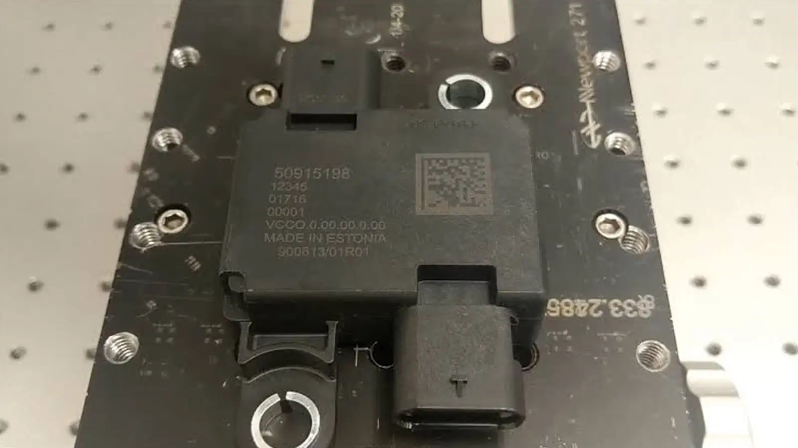
Automotive connector marking example
Automotive plastic connector component with laser-marked identification and a 2D traceability code.
This type of mark combines human-readable part information with a compact machine-readable code on the same plastic component. The available marking area, character size and code module size still need to be checked against the actual connector geometry and the reader used on the production line.
Engineering takeaway: the sample shows the kind of identification and traceability content used on automotive connector components; it does not by itself establish material grade, laser settings, code grade or durability qualification.
If your connectors serve electronics, communications or industrial equipment rather than automotive and EV, the Electronics & Electrical connector and terminal marking page is the better route for that task.
Marking Content
Marking Content and Code Requirements
The marking content drives the mark size, resolution and durability requirements of the task. Text needs legible character size; 2D codes need modules small enough to carry the data but large enough to read reliably; logos need consistent visual quality. The table below maps typical mark types on connector and plastic parts to their use and key requirements.
| Mark type | Typical use | Key requirement |
|---|---|---|
| Part number / date-lot code | Part identification, batch tracing, recall management | Legible character size and consistent contrast on the housing surface |
| QR / Data Matrix code | Compact data carrying, machine-vision reading at assembly stations | Code module size, contrast and readability — verified with a code reader or verifier |
| PIN-1 / TPA orientation marks | Mis-assembly prevention in connector assembly and harness build | Visible, consistent position; must not disturb the surrounding functional geometry |
| Logo / brand / ratings | Branding on housings and EV charging handles | Visual quality and consistency across the batch |
| Harness matching code | Pairing connectors with the correct harness branch | Readable by operators and barcode scanners on the line |
Code readability depends on the material, surface, mark size and verification method, so it is confirmed on real parts rather than guaranteed by the laser alone. When codes must be stored in a traceability system or read by line equipment, the marking task becomes part of a data chain; for PLC, MES, scanner and database interface questions, see the Traceability, PLC, MES & Data Integration solution.
Result Variables
What Determines Laser Marking Results on Automotive Connectors and Plastic Housings?
The resin name alone is not enough to predict a connector-marking result. The useful test window is shaped by the exact material formulation, the surface and geometry of the molded part, the amount of information that must fit in the marking area, and the acceptance criteria that the finished mark must meet.
- Exact grade and formulation — resin family is only the starting point; the specific grade can respond differently.
- Pigments, fillers and laser-sensitive additives — these can change absorption, contrast direction and the usable process window.
- Color, texture and surface treatment — molded texture, gloss, coatings and contamination can affect visual contrast and code reading.
- Wall thickness and local thermal mass — thin ribs and light sections have less tolerance for heat accumulation than thicker areas.
- Mark size and code module size — smaller characters and 2D modules demand tighter control of focus, spot size and position.
- Marking area and height variation — recesses, curves and part-to-part position changes affect focus and placement repeatability.
- Target appearance and surface condition — light or dark contrast, visible color change and allowable texture change must be defined before testing.
- Durability and functional limits — the mark must be judged against the real service and assembly requirements, not appearance alone.
Practical test input: send the exact production-grade part whenever possible. A material family name such as PA, PC, ABS or POM does not by itself define the final laser source, settings or machine configuration.
Target Result
What Marking Result Should You Target?
Define the passing result before comparing lasers. A connector mark is not successful simply because it is visible: the visual effect, code performance, surface condition, product function and required durability all need their own acceptance boundary.
| Result category | What to define | What a passing sample should show |
|---|---|---|
| Visual result | Light-on-dark or dark-on-light contrast, character size and acceptable batch consistency | The mark is legible under the intended inspection lighting without relying on an unusually favorable viewing angle |
| Code result | Code type, module size, reader/verifier method and project-defined acceptance grade | The code reads reliably with the production inspection method on the actual part |
| Surface result | Allowed color change, foaming or texture change, and what melting, residue or deformation is unacceptable | The required contrast is achieved without unacceptable surface damage around the marking zone |
| Functional result | Protected sealing, mating, latch, retention and terminal-insertion functions | The marking process does not create a measurable or visible problem in the functions covered by the product validation plan |
| Durability result | Applicable handling, abrasion, heat, fluid, cleaner or thermal-cycle conditions | The mark remains acceptable after the agreed project-specific durability checks |
Foaming, carbonization or another material-response mechanism may help create contrast, but those mechanisms are not the final acceptance target. The target is the measurable visual, readable, functional and durable result required on the finished connector or housing.
Geometry & Functional Surfaces
Part Geometry and Functional Surfaces — Where It Is Safe to Mark
On a connector or plastic housing, where the mark is placed matters as much as the mark itself. Connector parts are small, and much of their surface is functional: mating faces, sealing surfaces and latch areas must not be damaged by marking energy. Mark placement is therefore an engineering decision, reviewed against the part drawing before a configuration is selected.
Typical geometry on connector and plastic parts
- Small flat faces — the preferred marking area when a flat landing surface exists on the housing or cover.
- Recessed cavities and standoffs — marking inside pockets or between ribs; reach and focal length must be checked.
- Curved and cylindrical housings — circular connector bodies and cylindrical covers; focus must be maintained over the curved surface.
- Thin ribs and molded features — low thermal mass means faster heat build-up; marking parameters must be reviewed to avoid melt, surface deformation or visible heat marks.
Functional surfaces to protect
- Mating and contact faces — the surfaces that touch the mating connector; marking here can affect fit or sealing.
- Sealing surfaces and seal grooves — where O-rings or gaskets seat; surface damage can create leak paths.
- Latch, pin-retention and terminal-insertion areas — mechanical features that must keep their dimensions and surface condition.
- Areas near thin-wall features — even a visually fine mark can cause warpage or embrittlement risk if energy is too high.
A flat, non-functional landing area is usually the safest first choice, but the final marking zone still depends on the material, mark size, energy input and service requirements. Confirm the selected area on the actual part, then verify that mating, sealing and terminal insertion remain within the product’s acceptance criteria.
How Does Part Geometry Affect Fixturing and Positioning?
| Part geometry | Typical example | Fixturing / positioning direction |
|---|---|---|
| Flat face, stable position | Housing top face, cover plate | Standard marking machine with a simple fixture |
| Cylindrical / circular housing | Circular connector body, round cover | Evaluate rotary / circumferential marking |
| Curved surface or height variation | Charging handle, contoured housing | Evaluate 3D curved-surface marking |
| Inconsistent part position or orientation | Random-fed small housings, terminals | Evaluate vision positioning |
| Conveyor-fed or in-line parts | Connector assembly line, harness line | Evaluate flying / online marking with trigger integration |
| Multi-position or automatic loading | High-volume connector cell | Evaluate automatic loading & multi-station marking |
These are geometry-driven fixturing and positioning starting points, not a final machine-selection decision. The final system configuration is determined later by combining sample-test results with production rate, tolerance, verification and integration requirements. For the system methods behind these directions, see Solutions; for machine families, see Products.
Technology Direction
Which Laser Direction Is Usually Evaluated for Connectors and Plastics
For automotive connector housings and molded plastic parts, four laser families are commonly evaluated. Use the table below as a first-pass source-selection guide. The final choice depends on the plastic grade, color, additives, surface state, target effect and — critically — how much heat the part can tolerate without functional damage.
| Laser family | Typical task on this page | Why it is evaluated |
|---|---|---|
| Fiber, Q-switched (~1064 nm) | Text, logos and codes on many molded plastics and coated parts | A common 1064 nm starting point where the plastic absorbs appropriately; actual contrast depends on formulation, color and additives |
| MOPA fiber | Contrast tuning, heat-sensitive parts, fine codes | Wider pulse-width and frequency control, which helps balance contrast against heat input on plastics |
| UV (~355 nm) | Heat-sensitive plastics, small characters, thin-wall housings | Often evaluated to reduce thermal impact on heat-sensitive plastics or very small marks; actual results still depend on the material and process window |
| CO₂ (wavelength per machine configuration) | Some plastic housings and non-metal parts | Well absorbed by many organic and non-metal materials; confirm the actual wavelength with the machine datasheet |
Heat input is one of the central variables on plastic parts. Longer effective heat input can increase the risk of darkening, melting, foaming or surface damage near thin walls and functional surfaces. That is why pulse control (MOPA) and shorter-wavelength sources (UV) are often part of the evaluation, and why the useful setting depends on whether the goal is contrast, color change or a shallow engraved mark.
How each plastic responds — absorption, foaming, carbonization, additive effects, color change — is a material question, not an application question. For PA / nylon, PC, ABS, POM, PET, silicone-rubber and coated plastics, see the Plastics & Polymers pages and the coated plastic page. For machine families, see fiber laser marking machines and UV laser marking machines.
Failure Modes
What Are the Common Failure Modes on Connector and Plastic Marking?
A failed sample is useful when it shows which variable needs to change. The defect should be connected to the material, energy window, optics, geometry, positioning or verification method before changing the machine concept.
| Failure mode | What may be contributing | What to test or review next |
|---|---|---|
| Weak or uneven contrast | Material formulation, pigment/additive package, textured surface, unstable focus or a narrow process window | Compare source direction and parameter window on the exact production-grade part |
| Unreadable or inconsistent 2D code | Low contrast, modules that are too small for the surface, focus variation, distortion or position repeatability | Review code size, marking field/optics, fixture or vision repeatability, and verify with the production reader |
| Melting, warpage or visible heat halo | Excessive effective heat input, thin walls, low local thermal mass or repeated passes | Reduce thermal loading and compare a laser/pulse strategy with a wider usable heat-control window |
| Excessive foaming, carbonization, residue or roughness | Material response is outside the desired surface-result window | Rebalance energy, pulse conditions and scan strategy against the defined target result |
| Mark position drift or partial defocus | Part movement, inconsistent orientation, recess depth, curved surface or height variation | Review fixture design, datum strategy, vision positioning, working distance or 3D compensation need |
| Damage near sealing, mating or latch features | Marking zone is too close to a functional surface or the process window is too aggressive | Move the marking zone where possible, tighten the energy boundary, and repeat functional checks |
| Batch-to-batch appearance changes | Color, formulation, additive, molding or surface-state variation between lots | Include representative production lots in validation and define the acceptable operating window |
Handling, Workflow & Data
How Does Laser Marking Fit Into Connector Production?
A production-ready marking station has to control more than laser scan time. The complete workflow covers part handling, identification or data input, positioning, marking, verification, pass/fail routing and transfer to the next process. On small connector parts, those non-marking steps can determine the real cycle time and the level of automation required.
- Loading and part presentation — manual loading, tray, feeder, conveyor or robot; orientation must be repeatable enough for the selected positioning method.
- Part / data identification — fixed content can come from the marking program; variable or serialized content may come from a scanner, PLC, MES or database interface.
- Positioning and focus — fixture, nest, rotary indexer, vision guidance or height compensation keeps the marking area in the required position and working-distance range.
- Marking — the selected laser route applies the text, code, logo or orientation mark within the approved process window.
- Verification — visual inspection or code reading confirms the required result after marking when the line requires closed-loop checking.
- Reject / exception handling — unreadable, missing or incorrectly positioned marks need a defined stop, reject, rework or manual-review path rather than continuing as accepted parts.
- Unload and downstream handoff — accepted parts move to assembly, packing or the next station together with any required traceability record.
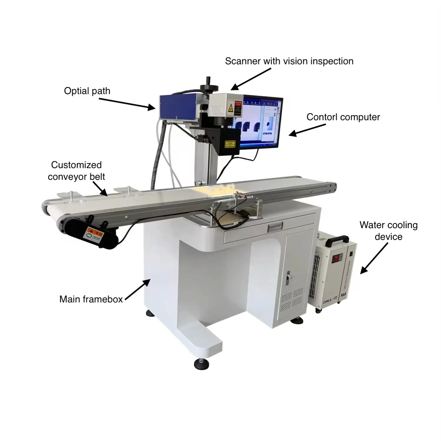
Representative conveyor and vision integration.
Representative conveyor and vision marking configuration; actual laser source, cooling and inspection architecture is project-specific.
Engineering takeaway: use this visual to understand the integration path, not as evidence of a specific customer installation or fixed system configuration.
When the required rate exceeds what a single operator can support, the evaluation may move from a standard machine to a configured line: rotary indexing for cylindrical parts, vision positioning for inconsistent orientation, flying / online marking for suitable conveyor-fed processes, and automatic loading & multi-station cells for higher-volume handling. If each mark must be linked to serialized production data, the traceability and data integration solution covers the code-to-database chain.
Cycle time therefore depends on handling, data exchange, positioning, marking, verification and reject logic as well as scan speed. A timed sample mark should be combined with the real loading method and the required inspection/data steps before deciding whether the project needs a standard workstation, a configured cell or in-line integration.
Before Production
What Must Be Validated on Real Parts
Final acceptance should be based on real parts because contrast, code readability, durability and functional impact vary with grade, color, geometry and the marking window. Before committing to a configuration, validate at least the following:
- Contrast and legibility — is the mark readable in the lighting and at the size the line requires?
- Code readability — verified with the same reader or verifier grade used in production.
- Heat exposure — if the part sits in an engine compartment or near heat sources, does the mark survive?
- Fluids, solvents and cleaners — engine oil, coolants, brake fluid, washing agents — does the mark remain legible?
- Thermal cycling — does the mark hold across hot-cold cycles in service?
- Abrasion and wear — handling, mating cycles and assembly friction must not erase the mark.
- Functional integrity — mating, sealing and terminal-insertion functions must be unaffected by the marking process.
How readability is confirmed on plastic parts
Marked plastic parts should be checked under the lighting used on the production line, with the same reader or verifier type used downstream. A batch code or Data Matrix should meet the acceptance grade defined by the customer or applicable application standard on the actual part. ISO/IEC 15415 is a common 2D symbol quality measurement method, while direct-part-marking applications may use the DPM-specific methodology in ISO/IEC 29158.
Where engine oil, coolants, brake fluid or thermal cycling are part of the service environment, durability should be verified against agreed test conditions before release. Functional checks such as mating, sealing and terminal insertion should also be performed by the party responsible for product validation.
Engineering takeaway: contrast, code reading and durability are validated on the actual part before production.
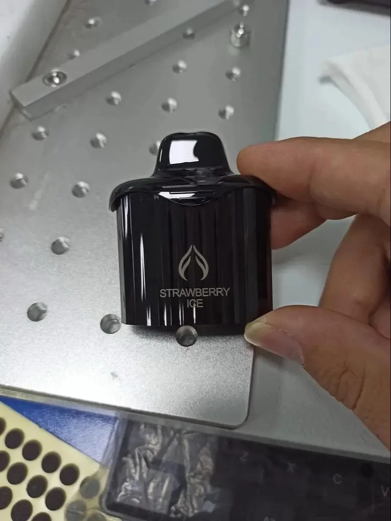
What a marked plastic sample can show
Representative plastic marking result on a dark plastic component; this image is not automotive connector evidence or durability proof.
The visible contrast, depth and color shift on a plastic part depend on the plastic grade or formulation, color, surface finish and laser source. The production result for an automotive connector still has to be confirmed on the actual connector material and geometry.
Engineering takeaway: use this sample only as a contrast example; do not infer automotive qualification, material grade or service-life durability from the image.
What to send for a sample test
- Material: grade, resin family, color, fillers or additives, surface finish (molded, textured, coated).
- Product: part photos or drawings, especially the area where the mark will sit.
- Marking content and size: text, logo or code; smallest character or module size.
- Target effect: contrast direction (dark or light), color change, depth, or a tactile mark.
- Production context: rate, line layout, whether marking is in-line or off-line, and any verification step.
- Quantity: how many samples and how many parts per year, so the evaluation matches the scale.
Acceptance criteria are agreed with the customer before production: what contrast, readability grade, durability test and functional check define a passing mark. Until those criteria exist, results are sample-test results, not guarantees. Zhuorui Laser assembles, configures and tests complete laser marking machines, and sample marking is a normal part of evaluating an application — contact us to arrange a test on your parts.
From Test to Machine
How Do Sample-Test Results Determine the Final Machine Configuration?
The machine configuration should follow the test result and the real production method. First confirm which laser route and process window can meet the target result on the actual part; then use geometry, positioning, cycle time, verification and data requirements to decide the optics, fixture and level of integration.
| Test or production finding | Configuration implication | Decision logic |
|---|---|---|
| One laser route achieves the required contrast with the best acceptable surface and heat result | Carry that source family into the final machine evaluation | The source is chosen from the passing process window, not from the material name alone |
| Small characters or 2D modules lose quality across a large field | Review field size, lens / optical setup and required working area | Code quality and usable marking area must be balanced before fixing the optical configuration |
| Flat parts repeat reliably in a simple nest | Standard workstation with a dedicated fixture may be sufficient | Do not add vision or automation when repeatable mechanical positioning already meets the requirement |
| Part orientation or mark position varies beyond fixture tolerance | Evaluate vision positioning or a stronger datum / fixture strategy | The positioning method should solve the measured repeatability problem |
| Curvature or height variation causes partial defocus | Evaluate part reorientation, rotary handling or 3D / height-compensation methods | Configuration follows the actual focus variation seen on the marked part |
| Mark quality passes, but manual loading cannot meet the required cycle | Evaluate indexing, conveyor handling, feeder/robot loading or a multi-station cell | Automation is justified by the full cycle, not by scan speed alone |
| Every code must be checked before the part leaves the station | Add the required reader / vision verification and pass-fail interface | Verification becomes part of the machine cycle and acceptance logic |
| Mark content is serialized or supplied by production systems | Add the required PLC, scanner, MES or database interface after project review | The data source and handshake must be defined before final software and I/O scope are fixed |
| Fume, residue or process by-products need controlled removal in the selected process window | Include suitable extraction and enclosure provisions in the system review | Process control and workplace protection are part of the complete machine configuration |
The final equipment brief should now be specific: exact material and surface, required mark and acceptance result, approved laser direction, marking field, fixture or positioning method, production rate, verification/data requirements, and any automation or extraction needs. That is the point where a machine model and project configuration can be selected without guessing from the application name alone.
FAQ
Common Questions About Connector and Plastic Laser Marking
Will laser marking burn or deform my plastic connector housing?
Heat control determines whether a mark stays clean or damages the surface. Plastics respond to absorbed energy differently, and thin walls and functional surfaces are more sensitive. Parameters are chosen for the specific grade and part, and sample marking can confirm the visual marking response. Product-function checks such as mating or sealing should be verified separately by the party responsible for product validation. Material-response details belong on the plastic material pages.
Which areas of a connector should not be marked?
Mating faces, sealing surfaces and seal grooves, latch and pin-retention areas, and terminal-insertion zones are usually protected from marking energy. The safe marking area is reviewed against the part drawing before configuration; in most cases a flat landing area away from functional surfaces is preferred.
Should I use UV or fiber for plastic marking?
There is no single answer: it depends on the plastic grade, color, additives, mark size and heat sensitivity. UV is often evaluated when heat-affected-zone risk is high or marks are very small; fiber and MOPA are often evaluated for speed and contrast on many molded plastics. The directional table on this page is a starting point; the final choice is confirmed on samples.
Will the mark survive engine-compartment heat, oil and washing?
Survival depends on the material, the mark type and the environment. Heat exposure, oils, coolants, cleaning agents, thermal cycling and abrasion are validation items on real parts. The customer defines the durability criteria, and the validation plan should test the mark against those criteria before production. Responsibility for environmental or functional testing should be agreed for the project.
Can laser marking affect connector mating or sealing?
If the mark is placed on a functional surface or delivered with excessive energy, it can. Mark placement should avoid mating, sealing and insertion areas. After marking, mating, sealing and terminal insertion should be checked under the product-validation plan rather than assumed from the visual mark alone.
How do I start: sample test or quotation?
For a part in scope, sample marking on your actual material is the most reliable start: it can confirm contrast direction, visible heat effects and code readability under the agreed inspection method before an equipment decision. Contact us to arrange samples; for standard equipment with clear specifications, Request a Quote; for non-standard, automated or data-integration projects, use OEM & Custom Inquiry.
Next Steps
Start Your Connector and Plastic Marking Application
If your part is in scope, the natural next step is a sample test on your actual material, then a quotation. Contact us to arrange a sample test, or jump to Request a Quote.
You are in the right place when your part is an automotive or EV connector, plastic housing or harness component. From here you can arrange a sample test, request a quote for standard equipment, or open an OEM / custom project for in-line or automated marking.
To make a quotation faster, prepare: material and surface · part photos or drawings · marking content and size · target effect · production rate · automation or data needs · voltage and destination · sample quantity.