
Bearing Rings · End Faces · Approved Circumference Zones
Bearing Laser Marking
Plan a bearing marking process by defining the bearing family, material and surface condition, functional no-mark zones, required code or text, target result, part presentation, production rate and sample acceptance criteria before final machine configuration.
Bearing / Workpiece Scope
Define the Bearing Before You Define the Marking Process
The same code can behave very differently on a loose hardened ring, an assembled bearing with seals, or a coated bearing variant. Define two separate inputs first: the bearing family and the part state at the moment of marking.
Bearing Family
Identify the bearing design because ring geometry, available side-face width, orientation information and functional surfaces vary by family.
Ball-bearing families
Deep-groove, angular-contact and other ball-bearing designs can differ in side-face width, seal arrangement, orientation requirements and available non-functional marking area.
Roller-bearing families
Cylindrical, tapered and spherical roller bearings can introduce wider diameter ranges, directional information, different ring geometry and different access around shoulders and cages.
Thrust and special bearings
Thrust bearings, matched sets and special bearing assemblies may require face identification, orientation or matching information that should be defined before layout is created.
Part State at Marking
Separately define how complete, clean and accessible the bearing is when the laser process occurs.
Loose inner or outer rings
Loose rings usually offer the best access, but the drawing still needs to identify raceways, precision fits, seal interfaces and any surface that must remain untouched.
Open assembled bearings
Cages, rolling elements, grease and adjacent geometry can change beam access, fixture contact, debris control and inspection after marking.
Sealed or lubricated bearings
Seals, shields, protective oil and grease can restrict the available zone and create additional cleanliness, masking and post-mark inspection requirements.
Marking Location
Choose an Approved Bearing Marking Zone
This section answers the functional question first: where is marking permitted without compromising rolling, sealing, fitting or other bearing functions? Approve the surface and its no-mark boundaries before deciding how to focus, fixture or rotate the part.
Ring side-face marking
Often the most practical starting location for designation and traceability information when the face provides sufficient width and the drawing permits marking.
Outer-circumference marking
Treat an outer-diameter band as a candidate only when the drawing confirms that it is not a precision-fit, sealing, rolling-contact or otherwise protected surface. Approve the exact band and keep-out boundaries before process design.
Inner-circumference marking
Treat the bore as a candidate only when it is not a protected precision-fit or other function-critical surface. Approval should identify the exact permitted area; laser access alone does not make the bore an acceptable marking zone.
Protect the bearing function first
Raceways, seal seats, precision fits and other function-critical surfaces should be treated as no-mark zones unless the bearing drawing and engineering requirement explicitly allow otherwise.
Why this matters: published bearing-marking work notes that laser exposure can alter the surface and underlying microstructure of hardened bearing steel, and specifically advises against marking a raceway because of its rolling-contact hardness requirements. See US20120312783A1, Method of manufacturing a bearing component.
Why Mark Bearings?
Why Are Bearings Marked?
The reason for marking should be defined before the laser route. A branding mark, a production traceability code and an orientation mark can require different content, positioning and verification.
Identify the bearing
Brand, designation and product-family information help distinguish the correct bearing type during inventory, assembly, service and replacement.
Link the part to production data
Date, lot, batch, serial or 2D-code data can connect a bearing or ring to manufacturing, inspection and downstream records.
Support orientation or matched-part handling
Some bearing families use direction, matching or dimensional-reference information to support assembly, pairing or controlled installation.
Support inspection and release
Inspection, status or reference marks can help prevent mix-ups when their format, authority and relationship to the production record are clearly defined.
Marking Content
What Is Commonly Marked on Bearings?
Marking content should be tied to a real identification, traceability, matching or inspection task. Not every bearing needs every data type.
| Mark content | Typical purpose | Input needed | Acceptance check |
|---|---|---|---|
| Brand and bearing designation | Product identification | Artwork or font, character height, exact location and viewing direction | Correct content, position, contrast and legibility |
| Date, lot or batch code | Manufacturing traceability | Format, update frequency, data source and duplicate rule | Correct variable data and record association |
| Serial number | Unit-level identification | Character set, sequence source, trigger and rework rule | No duplicates, omissions or transcription errors |
| Data Matrix or QR code | Machine-readable traceability | Code size, payload, cell/module size (the width of one code cell or module), scanner, curvature and verification target | Verified readability with the intended reader and agreed grading rule when applicable |
| Orientation or matching information | Assembly, pairing or installation control for specific bearing types | Direction convention, matching rule, visible location and responsible production step | Correct orientation and no ambiguity after assembly or packaging |
| Dimensional-reference or inspection information | Quality, matching or process reference where required by the bearing specification | Required value or symbol, tolerance convention, revision rule and approved zone | Correct value, format and relationship to the inspection record |
Bearing-specific example: SKF documentation for some super-precision angular-contact ball bearings lists product designation, manufacturing date, serial number, Data Matrix code, thrust-face direction and dimensional-deviation information among the bearing markings. The exact content depends on the bearing family and manufacturer specification. See SKF bearing markings documentation.
Result Variables
What Determines the Bearing Laser Marking Result?
The bearing name alone does not select the process. A useful sample test records the material and heat-treatment state, surface condition, desired mark mechanism, geometry and production target together.
Substrate and hardening condition
Record whether the marked part is bearing steel, stainless steel or another substrate, and whether the ring is hardened or in a different manufacturing state. Heat-treated bearing steel requires stricter control of where and how the mark is created.
Finish, oxide, coating and oil film
Ground, polished, oxidized, plated or coated surfaces respond differently. Rust-preventive oil, grease or residue can also change contrast and process consistency, so the test surface should match production condition.
Contrast versus material removal
Define whether the target is a visible contrast mark, very shallow surface modification or measurable engraving. Do not optimize for depth unless the drawing or durability requirement actually needs depth.
Character size and 2D-code density
Small characters and dense 2D codes narrow the acceptable range for focused spot size (the effective laser spot at the work surface), focus, contrast and distortion. Code-cell/module size and the intended reader should be known before approval.
Zone, curvature and usable width
End faces, small bores and cylindrical surfaces change focus, field coverage, rotation needs and how much of the code can remain inside an approved zone.
Position tolerance and takt time
A mark that looks good on one stationary sample may still fail in production if loading variation, positioning error, rotary motion or the required takt time (the production time available per part) pushes the process outside its stable range.
Engineering implication: laser heating of hardened bearing steel can alter surface oxide and underlying microstructure. For that reason, the target surface effect and protected functional zones should be part of the acceptance plan rather than judged only by appearance.
Target Result
What Result Should You Target?
Define the acceptable result before comparing laser settings. Otherwise, a darker or deeper mark can look better while actually missing the bearing, code or production requirement.
| Target | Define before testing | How to verify |
|---|---|---|
| Visual contrast and legibility | Required appearance, viewing condition, minimum character size and acceptable variation | Controlled visual inspection or defined imaging method across representative samples |
| Machine-readable code quality | Code type, payload, module size, curvature, reader and required verification rule/grade when specified | Read with the intended production scanner or verifier before and after the agreed exposure test |
| Depth or surface profile | Specify measurable depth only when the drawing, durability or downstream process requires it | Use the agreed depth/profile measurement method rather than judging darkness as depth |
| Position and orientation | Approved zone, datum, angular orientation and placement tolerance | Check repeatability over the planned bearing-size and variant range |
| Surface integrity | Maximum acceptable roughness change, raised edge, burr, debris or heat effect for the application | Inspect the marked zone and confirm no effect extends into protected functional surfaces |
| Durability | Relevant exposure: oil, cleaning, handling, packaging abrasion, storage or later assembly | Apply the agreed exposure sequence and recheck legibility, code readability and surface condition |
| Cycle time | Target takt, marking time, handling time and verification time | Measure the complete process cycle, not scanner speed alone |
Geometry + Part Handling
How Do Bearing Shape and Loading Affect the Process?
Once the marking zone is approved, geometry determines how reliably it can be reached, focused, positioned and repeated. This section deals with process geometry and handling rather than deciding whether the surface is functionally allowed.
Diameter and ring width
Provide outer diameter, bore diameter and ring width for every planned bearing family. These dimensions set the fixture range, available optical access, working-area requirement and whether rotary positioning is practical.
Mark coverage and curvature
Specify a local mark, partial arc or full-circumference requirement within the already approved zone. Curvature changes focus and can distort characters or 2D cells if motion and marking are not synchronized to the surface.
Datum and orientation
Identify the face, shoulder, bore feature or other repeatable datum used to locate the mark. If angular orientation matters, define the reference feature and tolerance.
Assembly and physical access
Show seals, shields, cages, flanges and adjacent geometry that can obstruct the beam, restrict safe fixture contact, or make post-mark cleaning and inspection difficult after the approved zone has been chosen.
Manual, tray or line presentation
Define how the bearing arrives, which side faces up, whether it is already oriented and how the operator or automation prevents the wrong variant from entering the marking station.
Variant range and recipe selection
List the planned size range and how often products change. High-mix production may need faster fixture adjustment, stored recipes and stronger mistake-proofing.
Oil, grease, seals and cleanliness
State the real production condition before and after marking. Cleaning a laboratory sample differently from production can create a false process window, meaning a range of settings that appears stable in the lab but does not repeatedly pass the agreed acceptance criteria in production.
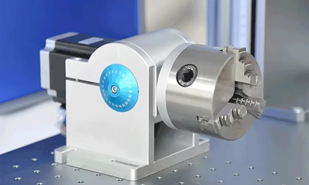
First-Test Laser Route
Which Laser Route Should Be Tested First?
Start with the actual bearing material, surface condition and target result. The table below is a screening route for sample testing, not a universal machine prescription.
| Workpiece / target | First screening route | Why start there | When to expand the test |
|---|---|---|---|
| Common steel or stainless bearing ring; text, serial or 2D code on an approved surface | Near-IR fiber laser | Fiber is a practical first route for many metal-marking tasks and is widely used for steel marking. | Expand the test if the required contrast, depth, code density, takt time or surface-integrity window cannot be met consistently. |
| Metal bearing where surface quality is sensitive or the acceptable process window is narrow | MOPA fiber comparison | MOPA is still a fiber-laser route, but adjustable pulse width can provide another process window for balancing contrast, heat input and surface effect. | Compare against the standard fiber baseline using the same material, finish, code and acceptance criteria. |
| Plated, coated, oxidized or otherwise layered bearing surface | Test the actual top layer and target mechanism | The process may need to preserve, modify or remove the surface layer. Base-metal identity alone is not enough to select the route. | Screen alternative sources only after the coating, thickness, color and required substrate exposure are known. |
| Full-ceramic, ceramic-coated or unusual bearing material | Material-specific sample screening | The word “bearing” does not predict how a ceramic or other special material will respond. | Compare suitable laser sources against the actual ceramic composition, finish, mark requirement and allowable heat/surface change. |
Practical first-test route: For conventional steel or stainless bearing rings, near-IR fiber is a sensible first screening route when the target is identification, traceability or controlled shallow surface marking. Compare a MOPA fiber process when pulse-width control may help widen the acceptable process window or reduce unwanted surface effect. This is a starting point for sample testing, not a universal prescription for every bearing material, coating or finish.
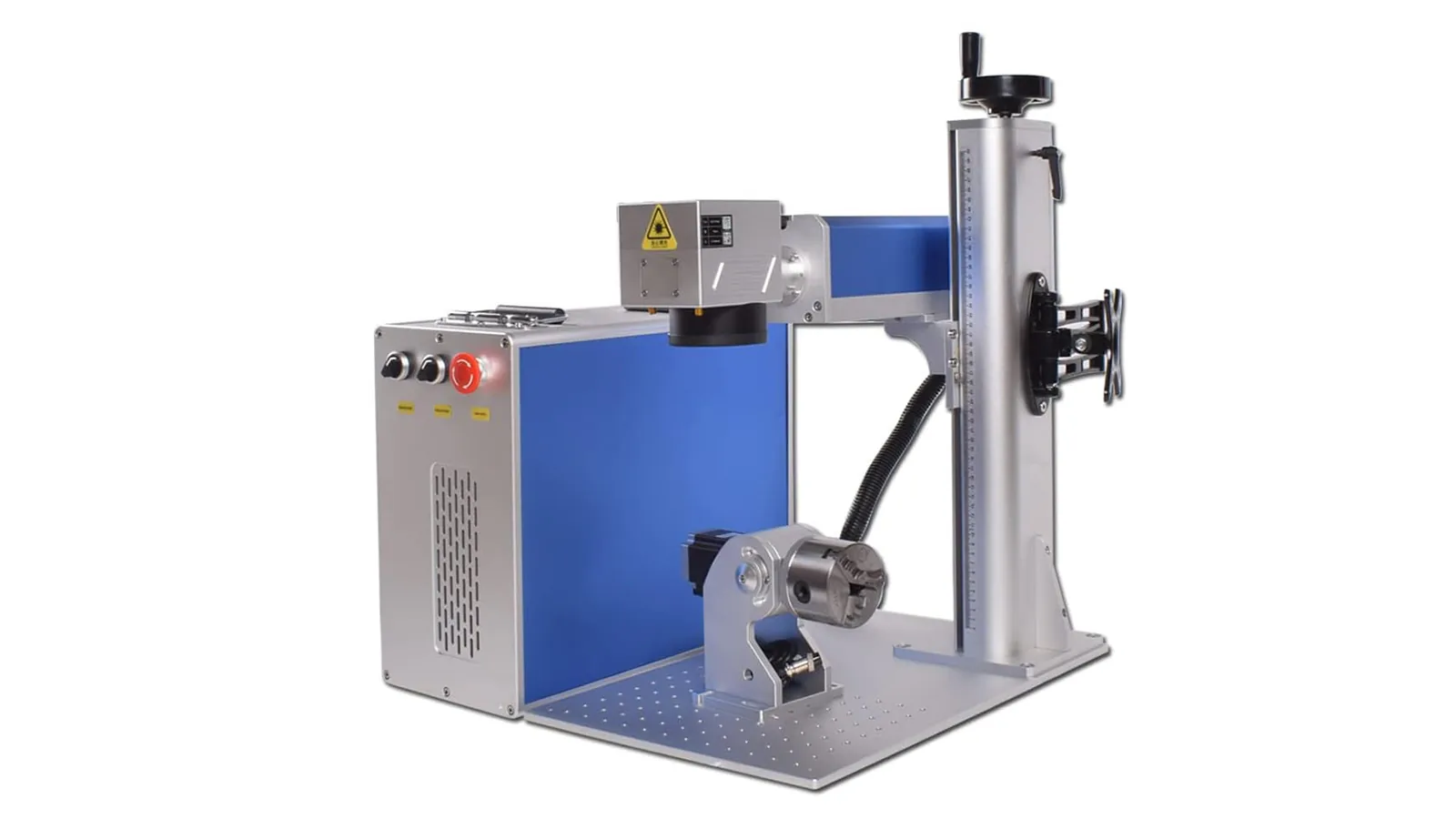
Failure Diagnosis
Common Bearing Laser Marking Failure Modes
A poor sample is useful when the failure is diagnosed. Record the symptom, isolate the likely variable and retest against the same acceptance criteria instead of changing several parameters at once.
| Observed problem | Likely drivers to check | First diagnostic action | Why it matters |
|---|---|---|---|
| Contrast varies from part to part | Oil film, cleaning variation, finish variation, focus or unstable process window | Compare cleaned and as-produced samples; record surface condition before changing laser settings | A process that depends on hidden cleaning differences will not remain stable in production |
| Rough, melted or raised mark | Excessive local energy, unsuitable pulse settings (for example pulse width and energy delivery), too many passes or unnecessary depth target | Reduce the required material removal first; compare lower-energy or different pulse-window settings | Raised edges, debris and excessive surface change can be unacceptable near precision bearing features |
| Characters or 2D code distort on a curved surface | Defocus across curvature, wrong field strategy, insufficient rotation synchronization or oversized mark area | Reduce the marked arc for a baseline, verify focus, then test coordinated motion if full coverage is required | Readable text can still fail machine verification when 2D cell geometry is distorted |
| Visible seam or stretched spacing around OD/ID marking | Rotary calibration, start/stop overlap, diameter input, acceleration or synchronization error | Mark a reference pattern and compare measured circumference/diameter to the motion recipe | Motion error can create duplicate, compressed or missing code elements |
| Mark position drifts | Weak datum, fixture clearance, inconsistent bearing orientation or wrong variant recipe | Measure fixture repeatability and confirm the production datum before changing artwork offsets | Position error can move an otherwise acceptable mark into a functional no-mark zone |
| Mark enters raceway, seal seat or precision-fit area | Incorrect zone definition, variant mismatch, datum error or artwork size growth | Stop the test and correct the approved-zone definition and mistake-proofing | This is a part-protection failure, not a cosmetic defect |
| Mark degrades after cleaning, oiling or corrosion-related exposure | Wrong target mechanism, insufficient durability, residue interaction or surface chemistry change | Repeat the agreed exposure sequence on representative samples and compare the mark before/after | Appearance immediately after marking does not prove durability in the real process |
| Serial or code data is duplicated or mismatched | Trigger timing, rework logic, recipe/data mismatch or failed verification handshake | Trace one test batch from source data through marking, verification, reject and rework records | Traceability fails even when the laser mark itself looks perfect |
Do not treat heat effect as only a color problem: published work on laser-treated bearing steels shows that thermal input can change microstructure and hardness. The exact effect depends on process conditions, so bearing marking should be qualified against the actual functional surface and acceptance criteria rather than judged by appearance alone.
Production Workflow
How Does a Bearing Marking Process Enter Production?
Production readiness means the correct bearing is loaded, positioned, marked, verified and recorded repeatedly at the required takt time. The laser exposure is only one step in that loop.
Load the correct bearing
Define manual, tray, feeder or line presentation and prevent the wrong bearing family or side from entering the process.
Identify the variant and recipe
Select the correct artwork, laser recipe, mark location, diameter/rotary data and variable-data format for the bearing being processed.
Position and orient
Locate the approved datum, establish angular orientation if required and verify that the protected no-mark zones remain outside the marking field.
Mark the approved zone
Apply the validated process window, including any required indexed or rotary motion, without changing the sample-approved surface effect.
Verify the result
Check presence, position, text or code content, readability and any required scanner result before the part leaves the station.
Handle reject, rework and data
Define what happens after a failed mark or failed read, how duplicates are prevented and how the accepted result is associated with the production record.
Cycle-time check: validate the complete load → position → mark → verify → unload/reject sequence. Scanner speed or laser marking time alone is not the production takt.
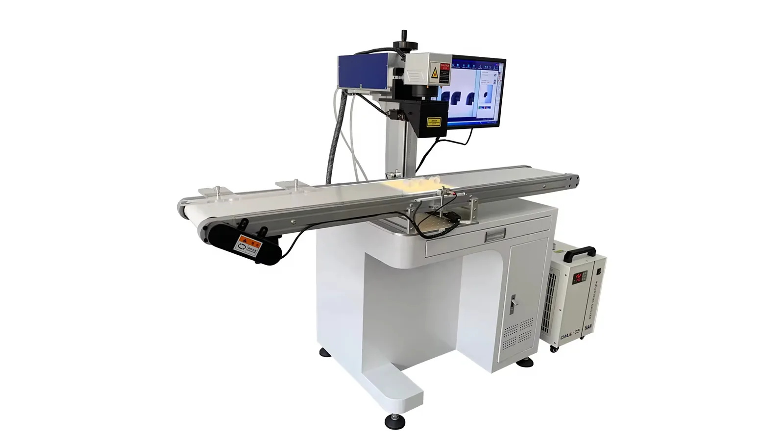
Sample Acceptance
How Should Bearing Samples Be Approved?
A bearing trial should be accepted against documented identification, readability, surface-integrity, durability, position and cycle-time criteria. “Permanent” is not a complete test specification.
Use representative production samples rather than only the easiest bearing to mark. The test set should cover meaningful boundaries such as size range, actual finish, real oil/cleanliness condition, intended marking zone and the main variants planned for production.
If depth or surface profile matters, define the measurement method. If the project does not require depth, do not convert a visible marking problem into unnecessary engraving.
Test Result → Machine Configuration
How Does the Sample Test Determine the Final Machine Configuration?
The final machine should be configured from the proven process window and production method, not from the word “bearing.” Each sample-test result removes uncertainty from a specific configuration decision.
| Test result or production input | What it determines in the machine configuration |
|---|---|
| Material, hardening state and surface response | Laser-source family and pulse strategy (the selected pulse-width, frequency and energy-delivery approach) to be carried forward from the proven sample route |
| Required contrast or depth together with takt time | Required power range, number of passes and stable process window rather than selecting power from appearance alone |
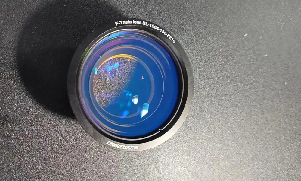
| Character size, Data Matrix module size and required working area | Optics, marking field size (the area covered by the selected optics at one setup), focused-spot/beam-quality requirement and the acceptable relationship between marking area and code detail |
| OD, bore, arc coverage and focus behavior on curvature | Fixture, rotary/indexing method and focus strategy for side-face, OD or ID marking |
| Variant count, position tolerance and orientation requirement | Changeover method, recipe management, mistake-proofing and whether part detection or vision assistance is needed |
| Scanner or verifier acceptance | Reader/verifier selection, verification trigger and pass/fail communication |
| Batch size, production volume, duty cycle and takt | Manual, semi-automatic or inline architecture plus loading, guarding, extraction and station capacity |
| Serial, lot, recipe and traceability data flow | I/O, PLC, database or manufacturing execution system (MES) interface requirements, including duplicate prevention and rework handling |
Practical rule: if a machine feature cannot be traced back to a proven sample requirement, part-handling need, verification requirement or production constraint, it should not be added automatically. If a sample result fails, the configuration should not be frozen until the failure mechanism is understood.
Sample and RFQ Inputs
Send the Information That Changes the Decision
Bearing, material and geometry
Send the bearing family and representative part numbers.
- Material, heat-treatment state and surface finish/coating
- OD, bore, width and planned variant range
- Loose ring, open bearing, sealed or lubricated state
- Photos, drawings and all protected no-mark zones
Content and target result
Send artwork, text and variable-data format.
- Mark size, location, arc coverage and position tolerance
- Contrast, depth/profile requirement if any, and surface-integrity limits
- 2D-code payload, module size, scanner and verification target
- Oil, cleaning, abrasion, storage or other durability tests
Handling, capacity and data
Send batch size, production volume and target takt time.
- Manual, tray, feeder or line presentation
- Orientation, changeover and mistake-proofing needs
- Data source, serial/rework rules and inspection workflow
- Destination, voltage, enclosure and integration constraints
Next Step
Evaluate Your Bearing Marking Requirement
Share representative bearings, the exact approved marking zone, material and surface condition, artwork or variable data, target mark result, production rate and the tests the mark must pass. Zhuorui Laser can use those inputs to build a sample-test path and translate the proven result into the required laser, optics, fixture, rotary, verification and integration configuration.