
Aerospace Data Matrix · Verification · Traceability
Aerospace Data Matrix Marking
Aerospace Data Matrix marking is not only about producing a small machine-readable code. The complete task is to place the correct approved data on the correct part, inside the allowed marking zone, with an acceptable surface effect, a defined verification result, and the production records needed to maintain traceability.
The engineering path should therefore start with the actual workpiece, final surface, encoded data, mark-zone limits, target result, loading method, throughput, verification rule, and durability requirement. The first laser route is then screened on representative samples, and the final machine configuration follows the test result rather than being chosen from the word “aerospace” alone.
Which Aerospace Parts Commonly Need Data Matrix Identification?
Data Matrix identification is most relevant when an aerospace workpiece needs a compact, controlled identifier that can be tied to the correct production or lifecycle record. The exact part type does not determine whether laser marking is permitted, but it helps define the marking area, handling method, and qualification conditions that must be evaluated.
- Machined housings and brackets: often provide a defined identification zone but may include pockets, ribs, radii, or finished surfaces that constrain where the code can be placed.
- Fasteners, fittings, valves, and fluid-system components: may have very limited marking area, cylindrical geometry, or controlled functional surfaces that make location and fixturing critical.
- Actuation and mechanical components: may require serialized identity while also imposing drawing-defined restrictions on where a permanent mark is allowed.
- Connector bodies and electrical or mechatronic housings: may combine small marking zones with mixed materials, coatings, molded surfaces, or orientation-sensitive loading.
- Small precision metal components: can make symbol density, cell definition, focus stability, and repeatable presentation more demanding than on a large flat plate.
- Serialized replacement or service parts: may need the physical identifier to remain correctly associated with controlled inspection, maintenance, or lifecycle records.
Important: a typical workpiece category does not authorize laser marking. The engineering drawing, customer or contract requirement, material and final finish, approved process, and applicable quality procedures determine whether the proposed direct-part mark is permitted.
Why Are Aerospace Parts Marked with Data Matrix Codes?
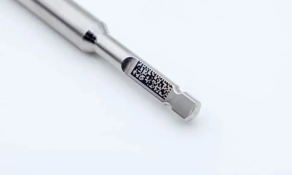
Aerospace Data Matrix marking gives a compact, machine-readable identity that can support serialization, part identification, lot control, and traceability when marking space is limited.
The key requirement is not only that the code looks clear, but that the correct data is placed on the correct part, in the approved location, and remains linked to the required production record.
What Information Is Usually Encoded in the Data Matrix?
Start with the real released data structure, including the longest expected string. More encoded characters can increase symbol density and reduce the available cell size (the dimension of each individual Data Matrix module) inside the symbol envelope (the maximum width and height available for the complete code).
| Information type | Typical role in the marking task | What must be controlled |
|---|---|---|
| Part number or item identifier | Identifies the part family or controlled item | Released format, revision relationship, and approved data source |
| Serial number | Creates unique part identity where serialization is required | Number creation, duplicate prevention, retry handling, and consumption rules |
| Lot or batch identifier | Connects a part to a production group or material/process lot | Approved syntax and correct work-order association |
| Supplier or manufacturer identifier | Supports source identification when required by the program | Approved identifier and formatting rules |
| Customer-defined data string | Supports program-specific identification or traceability logic | Character set, separators, prefixes, required fields, and data validation |
The full manufacturing, inspection, maintenance, or lifecycle history does not need to be assumed to exist inside the symbol itself. In many workflows, the marked identifier is what links the physical part to the controlled record. The project requirement should define which fields are encoded directly and which records are associated through the traceability system.
What Determines the Aerospace Data Matrix Marking Result?
The laser source is only one variable. Feasibility and repeatability are determined by the interaction between the workpiece, symbol requirement, geometry, verification method, production sequence, and handling conditions. The process window is the range of settings and operating conditions that continue to produce an accepted result rather than only one good-looking sample.
| Decision variable | Questions to define before testing | Why it matters |
|---|---|---|
| Material and final surface | What is the substrate? Is it bare, anodized, painted, plated, conversion-coated, textured, polished, or otherwise finished? | Laser response, contrast, local surface effect, reflectivity, and process window can all change. |
| Data and symbol density | What are the longest and shortest real strings? What is the allowed symbol envelope and required human-readable text? | Data length and available area affect symbol size, cell size, optical resolution, and process stability. |
| Marking zone and geometry | Is the zone flat, curved, cylindrical, recessed, near an edge, or close to a controlled functional surface? | Geometry changes focus, access, distortion, fixture design, illumination, and verification presentation. |
| Process sequence | Does marking occur before or after machining, cleaning, blasting, heat treatment, anodizing, painting, passivation, assembly, or another finish? | Downstream processing can reduce contrast, fill cells, change reflectivity, or remove part of the mark. |
| Verification and durability requirement | Is the requirement decode-only, formal verification, dimensional inspection, content comparison, or a combination? What exposures must the mark survive? | The acceptance method determines what must be measured and what a successful sample actually means. |
| Production requirement | What are the batch size, takt time (required production pace) or throughput target, loading method, part mix, changeover frequency, automation level, and required data interfaces? | A stable sample process may still require different fixturing, controls, verification, or automation to become a production process. |
What Should an Acceptable Aerospace Data Matrix Mark Achieve?
Define the target result before choosing the final equipment. A qualified mark is not simply “dark enough” or “easy to scan.” The acceptance package should state what must be true about the data, location, optical result, surface condition, durability, and traceability record.
- Correct data: the released identifier and formatting rules are reproduced accurately.
- Correct part and location: the symbol is applied to the approved workpiece and inside the permitted marking zone.
- Required readability or verification: the mark meets the specified method and threshold, not only a casual scanner check.
- Acceptable surface effect: the process does not create an unacceptable change in the controlled material or finish.
- Required durability: the result remains acceptable after the defined downstream or lifecycle exposure tests.
- Correct record association: the mark, work order, verification result, and disposition are linked as required.
- Repeatable production result: representative variation in surface, loading, orientation, and part condition remains inside the accepted process window.
Readable Is Not the Same as Verified
A barcode reader answers a practical question: can that device decode the symbol under its current lighting, angle, optics, and software settings? A verifier is a controlled measurement device used to evaluate defined symbol-quality characteristics under a specified method; it is not simply another barcode reader. A symbol can read on one device and still fail the required verification rule.
Production verification should therefore define the verifier, lens or field of view, lighting method, calibration practice, part presentation, controlled software where applicable, acceptance threshold, sampling frequency, and whether the result must be stored.
- Use representative production surfaces, not only ideal flat coupons.
- Verify the longest or most demanding approved data formats during qualification.
- Separate content accuracy from optical symbol quality.
- Define what happens when the symbol reads but does not meet the required verification threshold.
- Define what happens when presentation, curvature, reflectivity, or orientation prevents a valid verification result.
How Do Marking Zone, Geometry, and Part Handling Affect the Process?
The nominal mark box is not always the usable area
Edges, radii, recesses, fastener zones, sealing surfaces, contact surfaces, machining allowances, coatings, and part-to-part tolerances can reduce the stable area available to the symbol. The drawing or approved work instruction should identify the permitted location and any keep-out zones.
Flat, curved, recessed, and small workpieces behave differently
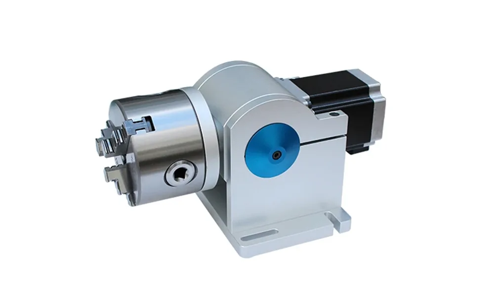
A flat accessible surface is easier to focus and verify than a curved bore, narrow flange, recessed pocket, or small cylindrical component. Curvature can change cell geometry across the symbol. Recesses can block the marking beam, illumination, or verifier view. Small parts can move during loading and may need a repeatable nest.
Stable positioning comes before unnecessary compensation
Define loading direction, datum surfaces (the reference surfaces or features used to locate the part), location tolerance, allowed orientation, and part-family variation. A stable fixture is often more effective than trying to compensate for an uncontrolled part with additional software. Autofocus, vision positioning, rotary motion, or three-dimensional focus control should be evaluated only when the geometry or production method actually requires them.
Which Laser Route Should Be Screened First?
Start from the real material and final surface, then choose a first screening direction according to the mark mechanism you are allowed to create. The table below is a starting logic for sample testing, not a universal aerospace recipe. Final source, pulse behavior, optics, and settings still have to be qualified on the representative workpiece.
| Actual workpiece / surface condition | First screening direction | What decides whether to keep that route |
|---|---|---|
| Bare or laser-responsive metallic surface | Start by screening a near-infrared fiber route. If tighter pulse-width control may help balance contrast, cell definition, and surface effect, include a MOPA fiber configuration in that screening. | Required contrast, cell geometry, permitted surface change, depth or texture limit, verification result, and repeatability on the actual alloy and finish. |
| Anodized, painted, plated, or otherwise coated metal | First define whether the required mechanism is color change in the top layer, controlled coating modification or removal, or marking of the substrate. Screen the laser route against that mechanism rather than against the base metal name alone. | Whether the coating remains within the allowed condition, whether the substrate is unintentionally exposed or damaged, and whether the final code survives the downstream process and verification requirement. |
| Polymer, paint, insulating layer, or another heat-sensitive surface | UV at 355 nm can be an early screening route when the actual material benefits from shorter-wavelength absorption or finer feature formation. A 1064 nm fiber route can still be viable for materials, pigments, fillers, or additives that respond well to it. | Contrast, melting or foaming, edge definition, cell uniformity, surface damage, verification result, and lot-to-lot material response. |
| Surface that responds poorly to the initial 1064 nm route | Consider whether a different wavelength is justified by the actual absorption and target effect. Green at 532 nm can be a screening candidate for selected reflective or absorption-challenging surfaces; it is not an automatic aerospace default. | Measured mark quality on the real substrate, permitted thermal and surface effect, symbol verification, and whether the alternative wavelength provides a wider stable process window. |
| Very small or high-density Data Matrix on any material | Screen the material-compatible source together with the optical field, spot formation, focus strategy, and positioning method. Do not treat wavelength as the only resolution variable. | Cell definition at the real symbol size, focus sensitivity, vibration, part-position variation, surface texture, and verifier presentation. |
Use the real requirement during screening
- Use the real surface. Record substrate, coating or finish, color, texture, reflectivity, and expected lot variation.
- Define the allowed process effect. Confirm whether local color change, coating modification, texture change, or material removal is permitted.
- Use the real symbol. Test the actual data density, symbol envelope, cell size, orientation, and adjacent human-readable text.
- Include the real geometry. Test on the actual flat, curved, recessed, or cylindrical marking condition when geometry can affect focus or verification.
- Compare routes against the target result. Judge mark formation, verification, surface effect, durability, and repeatability before selecting the preferred process window.
Optics and working field must support the required cell formation as well as the overall marking area. A larger field can reduce available marking resolution, while a small dense symbol can become more sensitive to focus, vibration, part position, and surface variation. That is why the first laser route and the optical configuration should be screened together when code density is demanding.
What Common Data Matrix Marking Failures Should Be Checked?
Failure diagnosis should begin with the observed symptom. Do not treat every problem as a laser-power issue; data control, fixture repeatability, surface condition, geometry, verification setup, and downstream processing can create different failure patterns.
| Observed problem | What to check first | Why it matters |
|---|---|---|
| The code reads but fails formal verification | Cell formation, contrast, surface reflectivity, presentation, lighting, verifier setup, and the specified verification method | Successful decoding does not prove compliance with the required verification rule. |
| Cells are uneven across the symbol | Focus, curvature, local height variation, fixture repeatability, and part position | Geometry and positioning can change the effective mark across the code even when one area looks acceptable. |
| Contrast drops after finishing or cleaning | Marking sequence, coating or finish interaction, downstream processing, and lifecycle exposure | A sample that looks acceptable before the next manufacturing step may not remain acceptable afterward. |
| The mark looks correct but contains the wrong data | Released data source, manual entry controls, program selection, and part confirmation | This is a traceability failure, not a laser-quality failure. |
| A duplicate identifier or wrong-part association appears | Serialization rules, duplicate prevention, retry logic, work-order association, and exception handling | A good optical mark can still create an invalid traceability record. |
| Contrast is strong but the surface effect is unacceptable | Allowed process effect, laser route, process window, and controlled surface requirement | The visually darkest mark is not automatically the correct engineering result. |
| Results vary between nominally similar parts | Surface lot variation, coating thickness, texture, fixture repeatability, focus, and loading orientation | Production robustness depends on the variation around the nominal sample, not only the best single result. |
What Must the Production Marking Workflow Include?
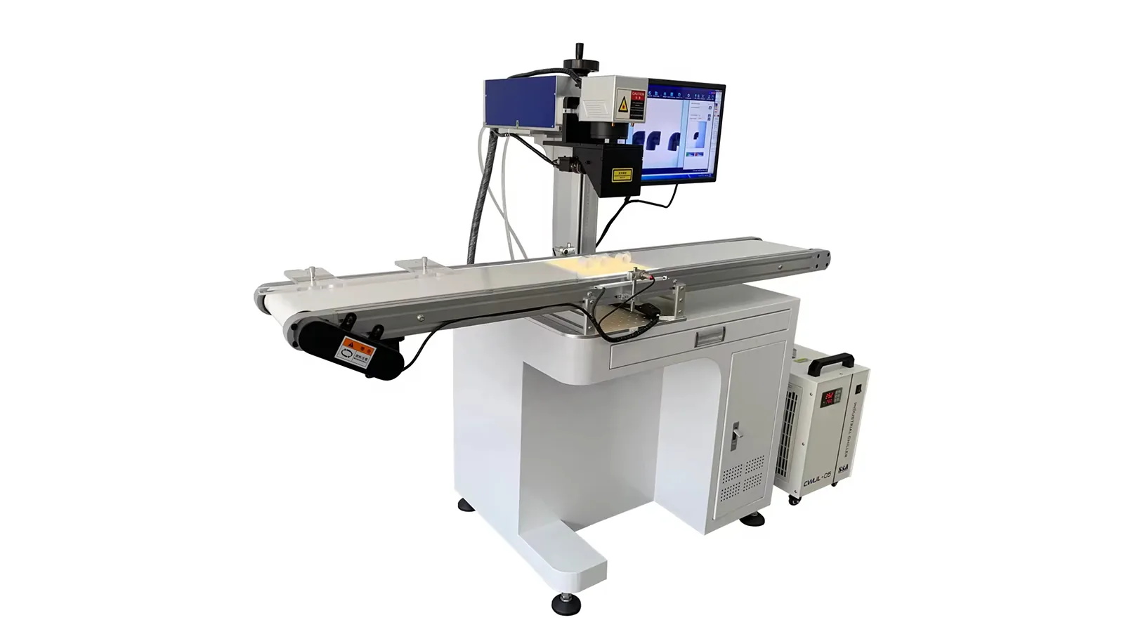
The production process must control the data and the physical part together. A robust workflow makes it difficult to mark the right code on the wrong part, reuse a consumed identifier, lose a failed verification record, or overwrite an exception without an authorized disposition.
- Release the approved data. Receive the correct identifier from the approved work order, controlled file, database, PLC, MES, ERP, or other authorized source.
- Confirm the part and program. Check the workpiece identity, drawing or revision where required, marking recipe, and allowed mark location.
- Load and position the part. Use the defined datum, fixture, orientation, and focus condition.
- Apply the mark. Run the qualified recipe and prevent unauthorized parameter changes.
- Decode or verify as required. Apply the defined reader or verifier method and capture the required result.
- Bind the mark to the record. Associate the part identifier, encoded content, work order, recipe revision, result, station, time, and other required fields.
- Disposition the result. Define pass, rework, reject, replacement, retry, or escalation rules before production begins.
Plan exceptions and rework before release
Decide how the process handles a duplicate number, wrong part, interrupted cycle, partial mark, failed verification, unreadable symbol, rejected part, replacement part, or approved rework. Do not automatically overwrite a failed mark or issue a new serial number without the authorized disposition.
How Should Representative Aerospace Samples Be Qualified?
The target-result section defines what the mark must achieve. Qualification should establish how that result was demonstrated on representative parts and preserve enough evidence to reproduce the accepted condition.
- Freeze the requirement package. Confirm the drawing, mark zone, real data strings, symbol envelope, material, finish, process sequence, verification method, threshold, sampling, record, and durability requirements.
- Test representative parts. Use the actual geometry and surface condition, including expected production variation. Coupons can support early screening but should not replace the final representative part when geometry or finish affects the result.
- Establish a controlled process window. Evaluate mark formation, data accuracy, position, focus sensitivity, surface effect, verification result, and part risk. Record the tested recipe, optics, and fixture condition rather than saving only the best-looking sample.
- Run downstream and lifecycle tests. Apply the required cleaning, finishing, abrasion, environmental, or other program-defined exposures, then repeat the required readability and verification checks.
- Confirm production controls. Verify data release, duplicate prevention, recipe access, part identification, inspection frequency, record storage, failure handling, rework authorization, and maintenance checks before release.
What Evidence Should the Qualification Record Preserve?
- Sample identity: part number or sample ID, material, finish, relevant lot or condition, and representative geometry.
- Real marking requirement: encoded data, symbol size, cell size, orientation, human-readable text, and approved mark zone.
- Tested process condition: laser route, controlled recipe, optics or field, focus condition, and the process window that was evaluated.
- Fixturing and presentation: datum, nest or fixture condition, loading orientation, and any rotary, focus, or vision method used during the test.
- Inspection evidence: content check, readability or verification method, equipment/setup used, measured result where required, and any dimensional or surface inspection.
- Exposure and reinspection: downstream finishing, cleaning, abrasion, environmental, or lifecycle test performed and the post-exposure inspection result.
- Production-variation evidence: relevant part-to-part, surface, orientation, loading, or lot variation evaluated rather than only a single ideal specimen.
- Accepted release condition: the recipe, fixture, verification method, production controls, exception rules, and change-control boundary that correspond to the accepted test.
A passed sample proves only the defined combination that was tested. It does not approve every alloy, coating, geometry, data density, or production condition. Changes that can affect the qualified result should be reviewed through the applicable change-control process.
How Do Sample-Test Results Determine the Final Machine Configuration?
The final machine should be configured from what the sample test demonstrates, not from a generic application label. The test reveals which process window, optics, positioning method, verification workflow, data interface, and production controls are actually needed.
| Sample-test finding | Configuration implication to evaluate | Decision boundary |
|---|---|---|
| The material and finish only meet the target result within one stable process window | Final laser source, pulse characteristics, power range, and recipe control should follow the qualified route | Do not transfer a sample result to another material or finish without review. |
| A small or dense symbol is sensitive to field size and focus | Evaluate optical resolution, field size, focus stability, vibration control, and positioning repeatability | Final feasibility still depends on the real symbol and surface condition. |
| Curvature or height variation changes cell formation | Evaluate fixture design, rotary handling, or controlled three-dimensional focus where justified | Use the simplest method that maintains the accepted result. |
| Loaded part position varies | Improve mechanical fixturing first; evaluate vision positioning when the remaining variation requires correction | Vision should solve a defined placement problem, not compensate for an avoidably unstable process. |
| Formal verification and saved results are required | Add a compatible verifier, controlled presentation, calibration practice, and record-storage workflow | The customer or program requirement defines the verification method and threshold. |
| Multiple parts, recipes, or frequent changeovers are required | Evaluate recipe management, part confirmation, fixture strategy, permissions, and changeover controls | Production complexity can drive system controls even when the laser mark itself is unchanged. |
| Released serialization must be tied to production records | Evaluate controlled file, database, PLC, MES, ERP, or other approved data interface and record association | The required architecture depends on the customer’s production and traceability system. |
| Throughput or automatic handling is a release requirement | Evaluate loading method, fixture count, trigger logic, automation level, and verification timing | Cycle-time feasibility must be demonstrated under the real production sequence, not inferred from laser scan speed alone. |
Which Standards and Customer Requirements Control Acceptance?
Data Matrix symbology, direct-part-mark verification, aerospace marking quality, and customer-specific implementation requirements are related but not interchangeable. The project team should identify which documents control symbol construction, marking method, verification, process approval, data content, and production records.
- SAE AS9132B: defines uniform Data Matrix quality and technical requirements specifically for metallic parts marking in the aviation, space, and defense industry. Laser is one of the marking processes covered. The standard does not define what information must be encoded; confirm program applicability and customer flow-down.
- ISO/IEC 29158:2025: direct part mark symbol-quality test specification used for defined DPM verification methods.
- ISO/IEC 16022:2024: Data Matrix barcode symbology specification.
- ISO/IEC 15415:2024: two-dimensional symbol print-quality test specification that may apply when required, rather than automatically replacing a DPM method.
Apply the correct order of precedence
The current contract, customer specification, engineering drawing, approved manufacturing plan, and quality-system procedures determine the actual acceptance path. Standards support the decision but do not authorize a mark location, material change, process deviation, or rework by themselves. Confirm the applicable revision and customer amendments before qualification or release.
Technical references
- SAE International — AS9132B: Data Matrix Quality Requirements for Parts Marking
- ISO — ISO/IEC 29158:2025, Direct Part Mark Symbol Quality Test Specification
- ISO — ISO/IEC 16022:2024, Data Matrix Bar Code Symbology Specification
- ISO — ISO/IEC 15415:2024, Two-Dimensional Symbol Print Quality Test Specification
Prepare a Representative Sample-Test Package
For a useful feasibility review, send the inputs that control the decision rather than only a product photo.
- Representative parts or controlled samples: include the real geometry when focus, access, or verification presentation can affect the result.
- Material and surface condition: grade, coating, finish, color, texture, and relevant lot variation.
- Drawing-defined marking zone: usable area, keep-out zones, locating datum or reference feature, and allowed orientation.
- Real data requirements: longest and shortest strings, symbol envelope, orientation, and human-readable text.
- Acceptance requirement: required standard or customer method, verification threshold, sampling plan, and saved-record requirement.
- Manufacturing sequence and exposure tests: cleaning, finishing, abrasion, environmental, or other lifecycle requirements.
- Production conditions: loading method, part family, batch size, throughput target, changeover needs, automation level, and required production-system interfaces.
The sample-test result should then be used to decide the final laser route, optics, fixture or motion method, verification setup, data interface, and production configuration.