Choosing the best laser marking machine for production means answering two questions in order: can the laser create the required mark on the actual material and surface, and can the complete machine repeat that accepted result at the required throughput? The answer cannot come from wattage, source type or machine style alone.
A laser may create an excellent sample but still be the wrong production choice once loading, positioning, data handling and inspection are included. A more powerful source may shorten the laser-processing step but do little for a station dominated by handling.
Vision, rotary motion, XY positioning or 3D focusing can be valuable when they solve a specific production problem, but they do not make a machine better simply because more functions have been added. A practical selection process therefore moves from process fit to cycle requirement, bottleneck, machine structure and final validation.
Confirm Process Fit First: Material and Mark Result Narrow the Laser Route
Laser marking machine selection should begin with the actual part rather than with wattage or machine style. The first screen is the material the beam will interact with, the condition of its surface and the physical result the mark must create.
Material and Surface Narrow the First Route
Broad labels such as metal, plastic or aluminum can narrow the first search, but they rarely define the final process. A metal part may be bare, anodized, painted or powder-coated, while two plastics from the same resin family can behave differently because of pigments, fillers or other formulation changes.
In many applications, knowing what is on the actual material and surface is as important as knowing the substrate underneath it. A coated workpiece may require the laser to alter or remove the surface layer rather than process the base material itself.
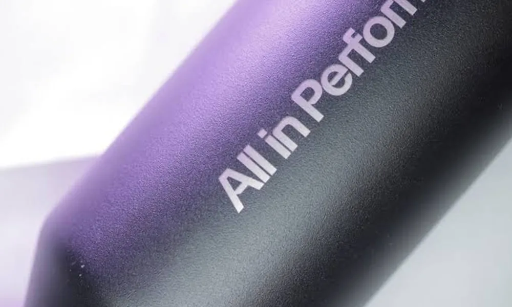
Wavelength and source characteristics are useful for first-pass screening, but they are not universal material rules. The comparison below narrows the routes worth testing while keeping the material, surface and required mark in view.
| Laser route | Typical wavelength | Useful first-pass applications | What can change the decision |
|---|---|---|---|
| Q-switched fiber | ~1064 nm | Many conventional metal marking and engraving tasks | Alloy, surface finish, coating, required depth or contrast, and thermal effect |
| MOPA fiber | ~1064 nm | Fiber-compatible tasks where wider pulse control may improve the required result | Whether a conventional Q-switched fiber process already meets the mark and cycle requirement |
| UV | 355 nm | Sensitive plastics, films, fine-detail work and applications where reduced thermal loading matters | Polymer formulation, pigments, additives, surface condition and target result |
| CO₂ | Common industrial options include 9.3, 10.2 and 10.6 μm | Paper, wood, glass and many organic or polymer applications | Exact material, coating or surface layer, absorption behavior and required mark mechanism |
Manufacturer specifications provide the wavelength references used here: JPT lists a 1064 nm center wavelength and independently adjustable pulse width and repetition frequency for its M7 MOPA fiber series; Coherent lists 355 nm for its Matrix UV platform; and Novanta/Synrad discusses 9.3, 10.2 and 10.6 µm industrial CO2 wavelengths and their material-dependent absorption. See the JPT M7 source specification, Coherent Matrix 355 datasheet and Novanta/Synrad CO2 wavelength guidance. These source specifications help screen the laser route; they do not define complete-machine performance on a particular part.
The Required Mark Can Change the Process
The same base material can require different laser processes when the target result changes. A stainless-steel part that needs a dark, low-removal mark presents a different problem from the same material requiring measurable engraving depth.
A coated component may need the surface layer removed without unnecessarily processing the substrate. A plastic housing may need a high-contrast color change while preserving a fine surface finish. Asking only whether a material “can be laser marked” collapses these different objectives into one question.
MOPA is especially easy to classify incorrectly. It is not a separate wavelength family alongside fiber, UV and CO₂; it is a fiber-laser architecture. Its additional value comes from greater control over pulse behavior, which can open a different process window when the required result is sensitive to pulse duration and thermal interaction.
After this screening, one or two laser processes should remain for testing on representative parts. Projects that still need a broader comparison of wavelength, pulse behavior, optics and field size can use our laser marking machine selection guide. Once a viable process route is established, the production decision shifts to cycle requirement, handling, bottlenecks and repeatability.
Translate Production Volume Into a Complete Cycle Requirement
Production volume becomes useful for machine selection only after it is translated into a time requirement. Saying that a factory needs 5,000 accepted parts per day does not reveal whether the laser needs to be faster, whether several parts should be processed in one fixture, or whether the larger opportunity lies in loading and handling.
Convert Production Demand Into a Required Interval
Required output first has to be related to the production time actually available. Suppose a process has 420 usable production minutes and must deliver 4,200 accepted parts. That gives 25,200 available seconds divided by 4,200 parts, or an average production requirement of one accepted part every six seconds.
That six-second figure describes the cadence the production system must support. It is not automatically the machine’s measured cycle time, because one cycle may complete one part, several parts in a fixture, or several marking positions on the same workpiece. If the 420-minute figure is scheduled run time rather than net usable production time, expected downtime and first-pass yield should be handled separately so theoretical cycle capacity is not mistaken for accepted output.
Build the Complete Cycle Around the Real Production Unit
For an industrial laser marking machine, laser-on time is only one part of the station cycle. The system may also need to load and locate the workpiece, move an axis, index a fixture, prepare variable data, inspect the result and unload the finished part.
Not every operation must happen in series. A dual-position indexing arrangement can allow one part to be loaded or unloaded while another is being marked, hiding some handling time behind the laser process. Product mix also matters because repeated changeovers spread setup time across fewer parts.
| Production input | Example or definition | Why it matters |
|---|---|---|
| Required good parts | 4,200 per shift | Defines the output that must actually be accepted, not merely marked |
| Net available production time | 420 min = 25,200 s | Provides the time available to satisfy demand |
| Required average interval | 25,200 s ÷ 4,200 = 6.0 s per good part | Defines the average cadence the system must support |
| Parts per fixture or cycle | Project-specific | Prevents the false assumption that one cycle always equals one part |
| Laser marking time | Measure on the representative mark | Shows only the laser-processing contribution to the cycle |
| Handling, motion and verification | Load, locate, index, inspect and unload as required | These steps can dominate actual throughput even when marking is fast |
| Changeover | Time per change × change frequency | Becomes important in high-mix or short-batch production |
| Overlapped operations | Identify which steps can run in parallel | Prevents overestimating the elapsed cycle by adding every step in series |
Once these inputs are known, “low volume,” “medium volume” and “high volume” are no longer precise enough for machine selection. If the complete cycle still cannot meet the required interval, the next task is to identify which part of that cycle is actually holding production back.
Find the Bottleneck Before You Change Power or Machine Features
A production shortfall can originate in the laser process, but it can just as easily come from loading, positioning, machine motion, inspection, data handling or changeover. Until those contributions are separated, adding power or machine functions is largely guesswork.
When More Laser Power Can Actually Help
Higher laser power becomes relevant when laser processing itself consumes a meaningful share of the cycle. In some applications, additional usable power can shorten processing time or reduce the number of passes needed to achieve the same accepted result.
Wattage alone is not a complete measure of processing performance. Pulse behavior, spot size, power density, scanning conditions and material response determine how effectively the available power can be used. A higher-power source is therefore something to evaluate inside a defined process, not a universal shortcut to higher throughput.
Scanner speed has the same limitation. Increasing speed only helps while the required mark remains inside its acceptance window. If the faster process loses contrast, changes depth, damages the surface or distorts small characters, the apparent productivity gain disappears.
When the Bottleneck Is Outside the Laser Process
The effect of attacking the wrong bottleneck is easy to see with a simple cycle. If a station spends three seconds marking and seven seconds loading, positioning and verifying the part, its complete cycle is ten seconds. Cutting the laser step from three seconds to 1.5 seconds only reduces the complete cycle to 8.5 seconds.
When non-laser operations dominate, machine architecture and workflow become more important than source power. Loading time may be reduced or overlapped, repeated positioning may be improved through a fixture or motion strategy, and significant data or verification time may require attention around communication and inspection.
Machine features should therefore follow a measured constraint. Vision, additional motion axes, rotary positioning and focus control are valuable when they remove a specific production problem; added without that problem, they can introduce setup or integration work without improving the step that limits output.
Match the Machine Structure to the Production Workflow
Laser source and machine structure solve different problems. Q-switched fiber, MOPA fiber, UV or CO₂ describes the laser-process route being used. Machine structure determines how the workpiece is loaded, located, moved, focused, marked and checked.
When a Simple Fixture or XY Motion Is Enough
For a stationary part with a repeatable location, stable height and a mark that fits inside one working field, a fixture-based workstation may already provide everything the process requires. Additional motion becomes useful when the laser must reach multiple locations that cannot be covered from one position.
Before specifying a larger optical field or additional XY travel, separate the overall workpiece size from the size of the actual mark. A large part with one localized marking zone may still need only a modest optical field if that zone can be presented correctly, while a genuinely large mark must still be checked against feature size, focus condition and the accepted result.
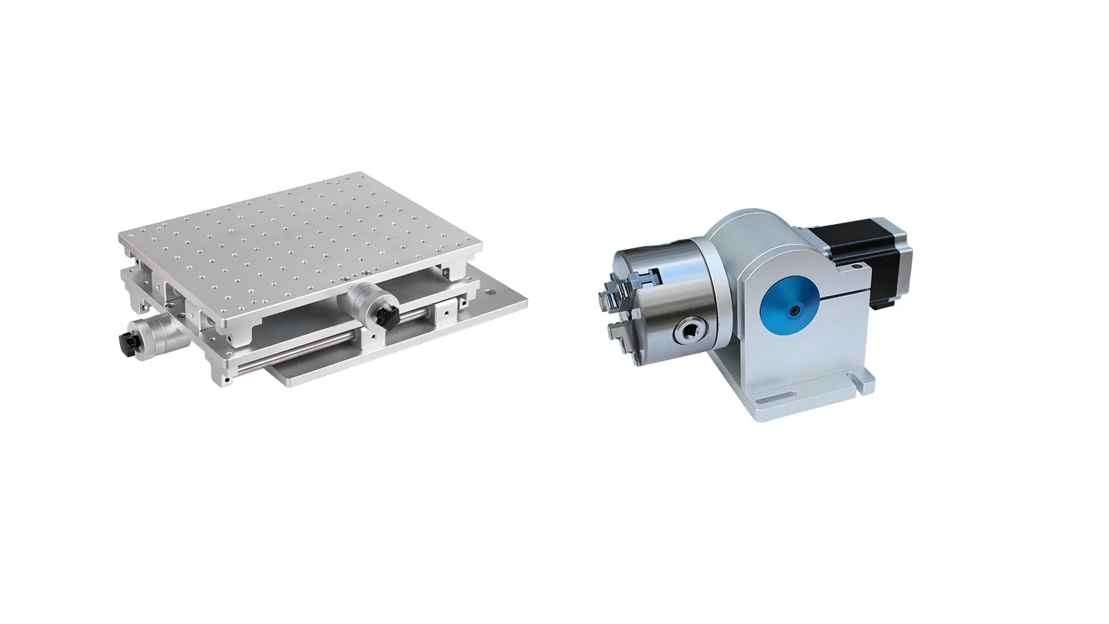
An XY or XYZ arrangement can move the workpiece or marking head through defined locations, whether the task involves a tray of components, a large part or several marking zones. The reason for additional axes is physical access and sequence, not batch size by itself.
Rotary, Vision, Autofocus and 3D Solve Different Problems
Cylindrical geometry introduces a different problem. When the required mark extends around a circumference, a rotary axis can turn the workpiece so the relevant surface enters the marking zone. That is different from a dual-position rotary or indexing table used to improve production flow.
Vision positioning addresses X/Y position or orientation variation. If the main variation is working distance, motorized Z adjustment or autofocus is the more relevant capability. If the mark itself spans substantial curvature, inclination or multiple Z levels, a 3D or dynamic-focus approach may be justified. KEYENCE’s technical documentation separately describes vision-based X/Y/Z/θ correction and 3D functions such as Z-tracking and surface mapping in its vision-guided marking and 3D laser marking pages.
| Production condition | Machine direction to evaluate | What it solves |
|---|---|---|
| Fixed part, repeatable position and stable height | Fixture-based workstation | Simple repeatable presentation without unnecessary motion or vision |
| Several parts or mark zones outside one static field | XY / XYZ motion | Sequential repositioning across multiple locations |
| Cylindrical circumference | Rotary axis | Rotates the workpiece so the required circumferential surface enters the marking zone |
| Variable X/Y location or orientation | Vision positioning | Finds the part and aligns the mark to its actual position |
| Variable part height | Motorized Z / autofocus | Restores the required working distance or focus position |
| Mark spans meaningful curved or multi-level geometry | 3D / dynamic focus | Handles Z variation across the actual marking path |
| Manual loading with tight cycle | Dual-position / indexing structure | Allows loading or unloading to overlap with marking |
| Product remains in motion during marking | Flying / on-the-fly marking | Synchronizes marking with moving-product flow |
When Production Flow Requires Indexing or Flying Marking
When parts are still manually loaded but the allowable cycle is tight, a dual-position or indexing arrangement may help by overlapping loading and marking. When the product must remain in motion, the requirement shifts to flying or on-the-fly marking.
Moving-line marking must account for the actual product motion, including detection, line speed, spacing, the available marking window and the timing relationship between the workpiece and the laser. Simply installing a laser beside a conveyor does not resolve those requirements.
Inspection may also belong inside the machine sequence. If a code or mark must be confirmed before the part leaves the station, camera placement, data flow and pass/fail handling become part of both the production architecture and the complete cycle.
Choose the simplest machine structure that reliably presents the part, reaches the required mark location, manages the variation that actually occurs from cycle to cycle and completes any required verification before the part leaves the station.
Validate Process Quality and Production Repeatability Before Finalizing the Machine
The first successful sample is an important milestone, but it is evidence of feasibility under the conditions tested, not proof that the complete production configuration is ready.
Define What an Acceptable Mark Means
A visually dark mark may be sufficient for one product, while another may require a particular engraving depth, limited surface disturbance, consistent location or a machine-readable code. Without an agreed definition of “acceptable,” sample comparison can easily turn into choosing the mark that simply looks best.
A code that can be decoded is not automatically equivalent to one that has passed a formal code-quality requirement. For direct-part-marked 2D codes, ISO/IEC 29158:2025 provides the current DPM symbol-quality test specification, while the applicable acceptance requirement still comes from the application.
Test Representative Production Variation
The parts used for validation should represent what the machine will see in production. Material formulation, coating, finish and geometry can all affect the process. This is particularly important for plastics containing pigments or additives, coated surfaces, or applications where material batches may not behave identically.
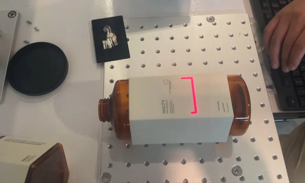
| Test route | Typical configuration | Why the longer run is used |
|---|---|---|
| 24 hours | Standard laser marking machines without complex added motion, vision or online functions | Checks basic whole-machine operation, laser marking, controller/galvo communication, software, cooling where applicable and electrical connections |
| 48 hours | Option-equipped systems such as CCD, motorized Z, XY, rotary, flying/online or 3D configurations | Additional modules create more motion, positioning, communication and control interactions that need repeated operation |
| 72 hours | Project-type machines with greater mechanical, multi-axis, vision, control or special-laser integration complexity | More integration variables create more potential failure points that may not appear during a short function check |
The 24-, 48- and 72-hour durations are Zhurui Laser’s internal stability-test routes. They are selected according to the confirmed machine configuration and project requirements, not used as a quality ranking or an industry-wide standard.
The proposed machine functions must be validated in the same way. A process that works on one carefully positioned sample may behave differently when parts are repeatedly loaded into a fixture, presented at different heights or located by a vision system.
| Validation level | What it proves | What it does not prove |
|---|---|---|
| Feasibility sample | The target effect can be created under the tested conditions | Production repeatability, full cycle performance or variation tolerance |
| Acceptance sample | The tested part meets defined criteria such as contrast, depth, location or code requirement | That the same result will hold across representative production variation |
| Representative validation | The process remains acceptable across relevant material, geometry or setup variation | Formal statistical process capability unless the required study is actually performed |
| Production-condition test | The combined workflow can repeatedly make accepted parts within the required complete cycle | All future material lots, environments or production conditions |
| Formal capability study | Statistical process capability against defined specifications when required | It cannot be inferred from a few successful samples |
Validate Quality and Complete Cycle Together
A configuration can make an excellent mark and still be the wrong machine if loading, positioning, marking, data handling and verification cannot meet the required output. Conversely, a faster cycle has no value if the change pushes contrast, depth, readability or surface condition outside the acceptance window.
Some applications also need to be checked after marking. If cleaning, coating, heating, sterilization or another downstream operation can alter the surface or readability, that condition should be included when it is part of the real acceptance requirement.
Once representative parts repeatedly meet the defined requirements under relevant production conditions and the complete cycle supports the required output, the final configuration can be selected with much greater confidence. That is still different from claiming formal statistical process capability unless the corresponding study has actually been performed.
The best laser marking machine is therefore not the machine with the largest specification sheet. It is the configuration in which the material and mark result support the chosen laser process, the complete cycle supports the production target, the machine structure resolves the actual handling and geometry constraints, and validation shows that the combined system can repeatedly deliver the result that matters.
If you are ready to compare actual machine families, review our Laser Marking Machines. If you already have the workpiece, target mark and production requirement, Request a Quote so the configuration can be reviewed against the real job rather than selected from wattage alone.