
WIRE, CABLE & TUBING APPLICATION
Heat-Shrink Tube Laser Marking
Define the tube formulation, shrink state, code, geometry, handling and production rate before selecting a laser route. A good sample must remain readable and acceptable after the required shrinking, assembly and downstream use.
WORKPIECE SCOPE
Which heat-shrink tube condition are you marking?
Define two separate dimensions before comparing laser sources or machine layouts: how the tube is supplied and handled, and when the mark is applied relative to shrinking.
Supply / Handling State
Continuous tube or reel
Reel-fed tube is presented continuously before cutting or recovery. Record the feed format and whether codes repeat at a fixed pitch.
Pre-cut sleeves
Individual sleeves are presented one at a time. Record sleeve dimensions and whether loading is manual or automated.
Marking Stage
Before shrinking
The mark is applied at the supplied dimensions and then evaluated after the specified recovery process.
After shrinking or installation
The final recovered or installed tube is marked in its service geometry; record access to the intended mark zone.
WHY MARK
Why are heat-shrink tubes marked?
The purpose of the code determines what must remain visible after shrinking and what the production system must control.
Part and harness identification
Identify a wire, cable, sleeve, assembly or connection point so production and service teams can distinguish the correct part.
Assembly guidance
Use polarity, rating, orientation, specification or customer text to reduce ambiguity during installation and maintenance.
Traceability
Apply lot, date, shift, reel, serial or other variable data when the process requires production history or item-level identification.
WHAT IS MARKED
What is usually marked on heat-shrink tubing?
Code format should be selected together with the available mark area, final tube curvature and the inspection method used after shrinking or installation.
| Marking task | Typical content | Application variables | Acceptance focus |
|---|---|---|---|
| Identification text | Part number, wire ID, size, voltage or customer wording | Character height, available length, tube diameter and contrast | Clear legibility in the final viewing condition |
| Batch or date code | Lot, date, shift, reel or production reference | Variable data, repeat pitch, changeover and restart behavior | Correct data and consistent placement |
| Polarity or specification | +, −, rating, color reference or assembly instruction | Orientation, spacing, final installation position and viewing distance | Unambiguous interpretation after shrinking and installation |
| Barcode or 2D code | Barcode, QR or Data Matrix where geometry permits | Module size, curvature, quiet zone, lighting and reader geometry | Verified machine readability in the required final condition |
RESULT VARIABLES
What determines the laser marking result?
Heat-shrink is a product form, not a single material recipe. The marking window comes from the interaction between the tube construction, the required mark and the way the part is processed.
Polymer and formulation
Base polymer, pigments, fillers, flame-retardant packages and other additives can change absorption, contrast mechanism and the amount of visible or thermal surface change.
Color and surface condition
Dark, light, opaque, glossy, matte or printed surfaces can respond differently. Surface contamination or existing print can also change the usable contrast.
Wall thickness and tube construction
Thin walls usually leave less tolerance for excessive local energy. Multilayer or special-purpose tubing should be tested as the actual supplied construction rather than treated as a generic polymer.
Diameter and shrink ratio
Supplied diameter, recovered diameter and shrink ratio affect available mark width, curvature and how text or codes change during recovery.
Code geometry
Character height, line length, stroke width, 2D-code module size and orientation determine how much dimensional change the code can tolerate.
Production condition
Line speed, repeat pitch, dwell time, focus stability, trigger timing and downstream shrinking or handling can turn a good static sample into an inconsistent production result.
TARGET RESULT
What should an acceptable heat-shrink mark achieve?
Define acceptance before testing. The target is not simply “a visible mark”; it is a mark that survives the required process while the tube remains fit for its intended use.
Code quality
- Correct text or variable data.
- Readable character size and sufficient contrast.
- Scannable barcode or 2D code where required.
- Placement remains within the allowed mark zone.
Tube and process integrity
- No unacceptable perforation, distortion, charring or residue.
- Mark remains acceptable after the specified shrink cycle.
- Required flex, rub, heat, handling or installation exposure does not invalidate the mark.
- Result remains repeatable at the required production rate.
GEOMETRY & HANDLING
How do tube geometry, positioning and production handling change the setup?
Once the workpiece state is defined, translate it into the setup requirements that control focus, positioning, feed, triggering and production repeatability.
| Workpiece or production condition | What changes | What to define before testing |
|---|---|---|
| Continuous reel-fed tube | Pitch accuracy, feed tension, line synchronization and restart consistency become critical. | Nominal/min/max line speed, repeat pitch, tube movement, encoder/trigger availability and cut location. |
| Pre-cut loose sleeve | Part orientation and repeat placement can dominate mark-position consistency. | Sleeve length, diameter range, loading method, fixture concept and required parts per minute. |
| Round or installed tube | Curvature changes focus, usable mark width and code distortion across the surface. | Outside diameter, accessible arc, mark orientation, focal tolerance and whether the part can be rotated or repositioned. |
| Mark before shrinking | The code may change size, spacing and curvature during recovery. | Supplied and recovered dimensions, shrink ratio, final mark location and post-shrink inspection method. |
| Mark after shrinking | Final assembly access and fixture clearance become primary constraints. | Installed geometry, surrounding components, available marking window, loading/unloading and final inspection position. |
| Higher-volume production | A sample result must be repeatable over the required duty cycle rather than only on isolated parts. | Parts/sleeves per minute, hours per shift, shifts per day, changeover frequency and acceptable verification/reject method. |
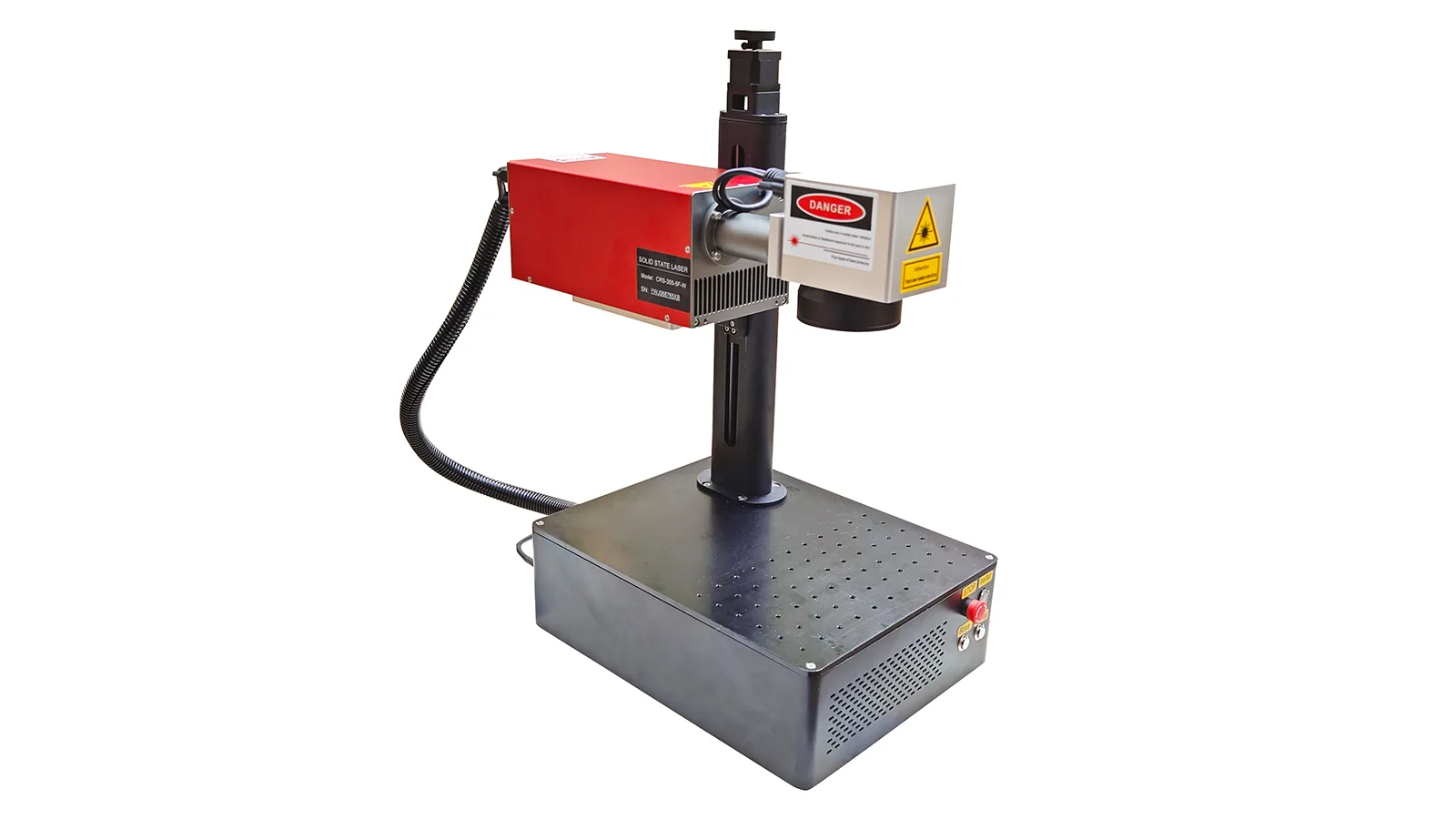
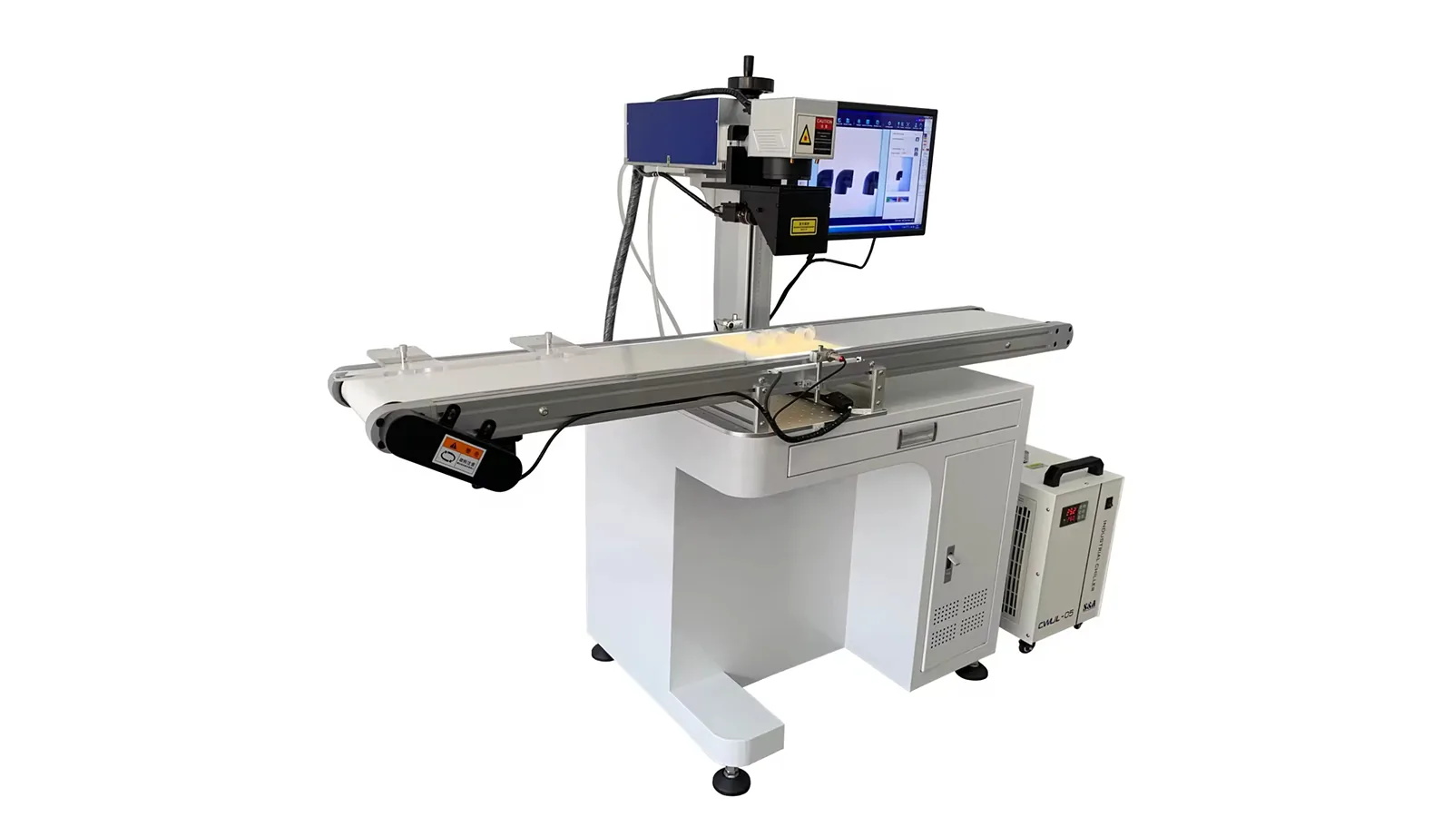
Architecture examples only: these machine images illustrate offline versus automated handling. They do not prove laser compatibility or a marking result on a specific heat-shrink formulation.
FIRST-TEST LASER ROUTE
Which laser route should be tested first?
Do not select a source from the words “heat-shrink tube” alone. Use the actual formulation, mark target and allowable affected area to decide the first screening route, then compare the sample result under the required shrink and production conditions.
| Starting condition | Route worth evaluating first | What the test must prove |
|---|---|---|
| Fine code, small mark area or thermally sensitive polymer where the affected zone must be tightly controlled | UV can be an early candidate on formulations that respond at this wavelength. | Contrast, edge quality, surface change, post-shrink readability and achievable cycle time. |
| Polymer construction that responds to controlled CO₂ surface interaction and where the required mark can tolerate that mechanism | CO₂ can be screened. | Contrast, distortion, penetration risk, residue/fume behavior, post-shrink integrity and speed. |
| Pigmented, filled or additive-modified polymer that shows useful near-infrared response | Fiber, including MOPA variants where pulse control is relevant, can be evaluated. | Contrast mechanism, heat effect, repeatability, required pulse window and post-shrink integrity. |
| Unknown formulation, multilayer tube or inconsistent supplier information | Material identification plus comparative sample screening is safer than assuming one universal source. | Which source creates an acceptable mark without unacceptable damage, then which process window remains stable after shrinking and at production speed. |
FAILURE MODES
Where does heat-shrink tube marking usually fail?
Failure diagnosis should separate material response from geometry, shrinking and production-control problems.
| Observed problem | Likely contributors | Check first |
|---|---|---|
| Readable before shrinking, poor after shrinking | Shrink ratio, code orientation, module/character size, recovered curvature or mark mechanism. | Compare supplied and recovered dimensions and inspect the same marked area after the specified recovery cycle. |
| Tube deforms, softens, chars or perforates | Excess local energy, unsuitable wavelength response, thin wall, repeated exposure or poor focus. | Inspect the affected area, reduce unnecessary energy input and compare another route if the required contrast cannot be achieved safely. |
| Good result on one batch, weak contrast on another | Formulation, pigment, additive, surface or supplier-lot variation. | Compare material identity, color and supplied condition; do not assume identical response from visual appearance alone. |
| 2D code is visible but will not scan reliably | Module size, curvature, deformation after shrinking, low contrast, lighting or reader geometry. | Verify with the intended reader in the final tube condition rather than relying on visual inspection only. |
| Static samples are good, production marks drift | Feed variation, trigger timing, repeat pitch, focus, tube rotation, line-speed change or restart logic. | Run the real or simulated production presentation and record position, code quality and timing over repeated cycles. |
PRODUCTION WORKFLOW
How does a validated sample move into production?
The process route depends on whether the tube is marked before recovery or after installation, but both routes need controlled positioning, data, verification and a defined reject response.
Typical production path
Feed or load tube → establish position and orientation → trigger the correct fixed or variable data → laser mark → perform initial inspection → cut/assemble if required → shrink under the specified process → verify the final mark → accept or reject.
Typical production path
Assemble and shrink → present the final geometry → locate the mark zone → trigger the correct data → laser mark → verify readability and tube condition → accept or reject → record the result when traceability is required.
SAMPLE ACCEPTANCE
How should heat-shrink samples be accepted?
A useful sample test records the tube identity, the process condition and the final acceptance result so the same evidence can be used to choose the production configuration.
Define the tube
Record material/formulation if available, color, wall thickness, supplied and recovered diameter, shrink ratio, surface condition and supplier/lot information when relevant.
Define the code
Use the real text or data structure, minimum character or module size, orientation, mark area, repeat pitch and the intended inspection method.
Run the real downstream condition
Inspect before and after the specified shrink cycle, then add required flex, rub, heat, handling, installation or other project-specific exposure.
Record acceptance
Document code correctness, readability/scannability, placement, surface integrity, repeatability and cycle-time result against the agreed project criteria.
FINAL MACHINE CONFIGURATION
How do sample-test results determine the final machine configuration?
The final machine should be configured from the validated process window and production method—not selected before the tube, code and handling conditions are proven.
| Validated test result or production input | Configuration decision it informs |
|---|---|
| Which wavelength/process gives acceptable contrast with acceptable tube change | Laser source family and required process-control range. |
| Required character size, 2D-code size and mark field | Optics, focal arrangement and working field. |
| Supplied/recovered diameter, curvature and accessible mark zone | Fixture, positioning method, possible rotary/3D handling requirement and working distance. |
| Continuous reel, cut sleeve or installed assembly | Online integration, offline workstation or dedicated loading/part-handling architecture. |
| Line speed, parts per minute, repeat pitch and cycle-time test result | Source/scanner performance requirement, encoder/trigger design and automation level. |
| Variable-data source and code-change frequency | PC/PLC communication, database or line-control interface and recipe management. |
| Required machine-readable verification | Barcode reader or vision verification and reject logic. |
| Observed smoke, residue or process by-products | Extraction requirement and enclosure/airflow planning. |
| Hours per shift, shifts per day, changeover frequency and production volume | Duty-cycle margin, workstation layout, loading strategy and final automation level. |
| Operator access and installation constraints | Guarding, enclosure, controls, workholding and line-integration layout. |
RELATED APPLICATION CONTEXT
See the broader wire, cable & tubing production route
Use the parent application page for cable, wire and tubing production scenarios, then use this page to define heat-shrink-specific material response, recovery behavior and acceptance.
NEXT STEP
Validate the tube, the code, the shrink condition and the production method
A useful test should prove the final mark and generate the information needed to select the laser source, optics, handling, verification and automation level.
Discuss Your Application