
Laser Marking Machine Applications · Online Product Coding
Wire, Cable & Tubing Laser Marking
Wire, cable, heat-shrink tubing, plastic tube and metal pipe can all require permanent identification, but the engineering task changes with material formulation, surface condition, diameter, line speed, mark size and how the product is presented. A useful feasibility review therefore starts with the real workpiece and target result, then tests the laser route, motion control and acceptance criteria together.
Request a QuoteReview Product Types
- Continuous and fixed-station marking
- Material and surface screening
- Position, speed and data control
- Sample-to-configuration validation
Application Decision
Start with the workpiece, result and line conditions
A laser source cannot be selected from the words “wire” or “tube” alone. First define the exact product, substrate and surface, what must be marked, the acceptable result, diameter or geometry, line speed or production volume, and how the mark will be triggered and verified.
A useful project brief should be specific enough to say: “We need this code on this wire, cable or tube surface, at this size and position, at this production speed, with these readability and durability requirements.” That information can then be converted into a first-test laser route, a sample acceptance plan and a final machine configuration.
Product Scope
Which wire, cable and tubing products use laser marking?
The product form determines the first handling and motion questions. Separate the workpiece type before evaluating the laser source or automation method.
01 · Wire
Wire Laser Marking
Continuous conductor or insulated wire coding for size, length reference, batch, product identity and production traceability. Record diameter range, line speed, repeat interval and the available mark window.
View wire application02 · Cable
Cable Jacket Marking
Mark cable jackets with ratings, part identity, lot information, sequential data or brand information. Jacket formulation, pigment, additives, wear and downstream handling can all change the result.
View cable jacket application03 · Heat-Shrink
Heat-Shrink Tube Marking
Identify heat-shrink sleeves before or after shrinking. The test must consider sleeve chemistry, shrink state, code distortion, contrast and whether the mark survives installation.
View heat-shrink application04 · Plastic Tube
Plastic Tube Laser Marking
Mark flexible or rigid plastic tubing with product, batch or position information while accounting for polymer formulation, color, curvature, line motion and any fumes or residue created by the process.
View plastic tube application05 · Metal Pipe & Tube
Metal Pipe and Tube Marking
Apply longitudinal, fixed-position or circumference marks to metal tube and pipe. Surface finish, coating, diameter, runout and whether the part moves or rotates determine the handling direction.
View metal pipe and tube application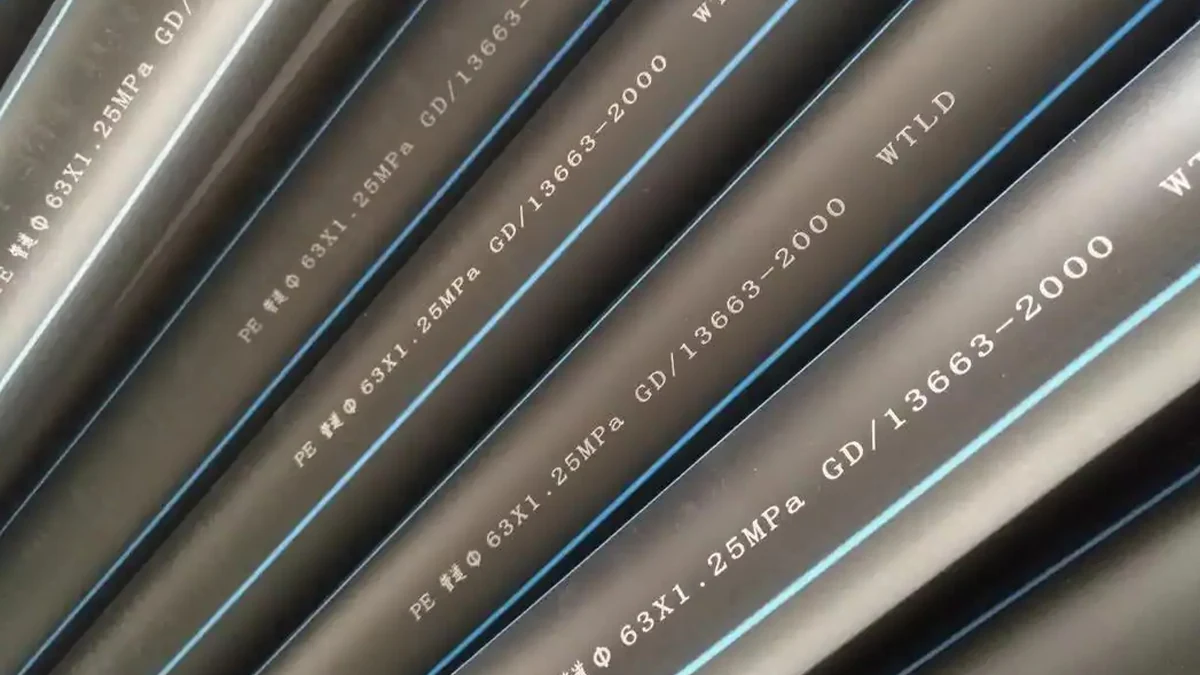
Why Mark
Why are wire, cable and tubing products marked?
The reason for marking determines what data must be controlled and how permanent, readable and repeatable the result needs to be. Laser is only one possible marking method; the business and production requirement comes first.
Product Identification
Identify wire gauge, cable type, tube specification, rating, material family or other product information that must remain associated with the workpiece.
Length & Installation Reference
Use meter, foot, cut-length or position references where installers, operators or downstream processes need to locate a point along a continuous product.
Batch & Production Traceability
Link the product to lot, date, shift, reel, line, serial or other production data so a finished item can be traced back to the active production record.
Brand & Specification Information
Apply manufacturer identity, model, rating, logo or customer-specified information where the finished surface must carry visible identification.
Installation & Service Identification
Keep product identity, specification or length references available when installers, technicians or maintenance teams need to identify the correct wire, cable or tube after it has left the production line.
Customer or Market Requirements
Some products require specific identification content, placement or durability for a customer specification or destination market. The applicable requirement should be defined before the marking process is approved.
What Is Marked
What information is usually marked on wire, cable and tubing?
A clean-looking mark is only one requirement. The production team must define what the code carries, how often it repeats, where it is read and what happens when the line changes product, reel, batch or speed.
| Marking task | Typical content | Application questions | Validation |
|---|---|---|---|
| Product identity | Part number, size, rating or specification | Required character height, contrast and repeat distance | Readability on the finished surface and after handling |
| Length and meter coding | Meter, foot, lot or cut-length references | Encoder source, interval accuracy and line-speed range | Measured spacing across minimum, nominal and maximum speed |
| Batch and serial traceability | Lot, date, shift, reel or sequential number | Data source, changeover rule and one-to-one product binding | Correct data follows the active recipe and batch |
| 2D code or compact code | QR, Data Matrix or encoded identifier where size allows | Module size, focal position, reader distance and orientation | Scanner or vision readability on representative samples |
| Brand or specified identification | Logo, rating symbol or required product information | Visible surface, permanence target and customer or market requirement | Durability and acceptance criteria defined for the project |
Customer-specific or regulatory identification requirements should be checked against the actual product, destination market and applicable standard. A laser sample can confirm process feasibility, but it does not by itself establish product compliance.
Result Variables
What determines the laser marking result?
Two products that are both called “cable” or “tube” can respond very differently. The result depends on the material and surface, but also on curvature, speed, code geometry and what happens to the product after marking.
| Variable | Why it matters | What to record |
|---|---|---|
| Polymer / metal / surface construction | The substrate, coating, printed layer or finish determines where laser energy is absorbed and what physical or color change is possible. | Exact material, grade or formulation when known; coating or printed layer; surface finish. |
| Color, pigment and additives | Different colorants, fillers and additives can change contrast, thermal response and batch-to-batch marking behavior. | Actual production color, supplier formulation or sample from each important variant. |
| Diameter, wall/jacket thickness, curvature and runout | Wall or jacket thickness can change how much local surface modification is acceptable before deformation or functional damage becomes a concern, while curvature and runout reduce the usable in-focus width and can weaken one side of a code. | Minimum and maximum diameter, wall or jacket thickness where relevant, roundness/runout, mark width and allowable position. |
| Line speed and motion stability | The process window must still deliver the full mark while the product moves, accelerates or changes speed. | Minimum, nominal and maximum speed; acceleration; line encoder or speed-reference method. |
| Character / code size | Small text and compact 2D codes are more sensitive to focus, spot size, motion error and edge definition. | Character height, line count, code size, module size and required read distance. |
| Repeat interval and mark position | Meter coding and repeated marks depend on synchronization between product travel and the marking trigger. | Repeat pitch, longitudinal tolerance, orientation and sensor/trigger reference. |
| Downstream process | Winding, abrasion, shrinking, bending, installation, cleaning or heat can alter readability or damage a marginal mark. | Real handling sequence and the durability checks required after marking. |
| Production variation | Changes in reels, batches, colors, suppliers or product sizes can move the process outside the proven window. | SKU range, changeover frequency and which variants must be represented in testing. |
Target Result
What marking result should you target?
“Visible” is not a complete acceptance standard. Define what a good result means before comparing laser sources or machine configurations.
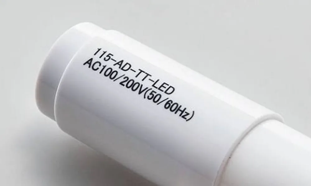
Readable Contrast
Text, symbols or codes should be readable under the intended viewing or scanning condition, not only under ideal bench lighting.
Surface Integrity
The required contrast should not come with unacceptable melting, charring, cracking, excessive foaming, coating damage or functional damage to the workpiece.
Position & Spacing
The mark should stay inside the allowed longitudinal and circumferential position window, with repeat or meter spacing controlled to the project requirement.
Correct Variable Data
Batch, reel, serial, date, meter or recipe-driven information must correspond to the product that is actually passing the marking station.
Required Durability
Where the application requires it, the mark should remain acceptable after representative abrasion, winding, heat, shrink, installation, solvent or handling tests.
Production Stability
The result should remain acceptable through the intended speed range and normal product variation, rather than being proven only on a stationary sample.
Geometry, Positioning & Handling
How do product shape and line handling affect the marking setup?
The same code can require very different positioning and motion control on a continuous cable, a flexible tube, a cut sleeve or a fixed metal pipe. Geometry should be defined before the machine layout is finalized.
| Product presentation | Handling direction | What must be confirmed |
|---|---|---|
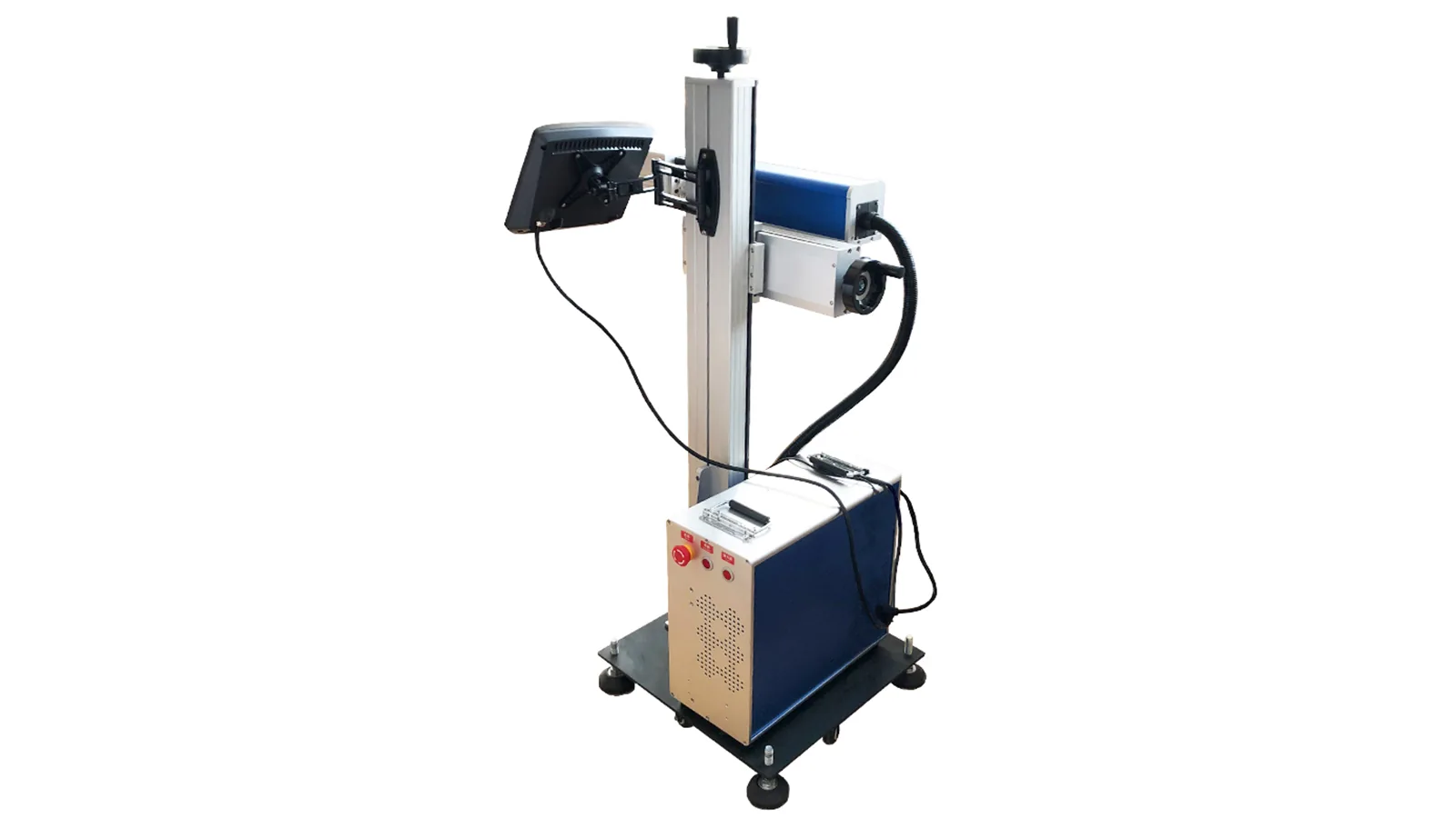
| Continuous wire or cable on an extrusion or take-up line | Online / flying marking synchronized to line motion; encoder and/or line/product trigger according to the control method. | Speed range, mark window, sensor location, repeat interval, product vibration and line I/O. |
| Flexible plastic tube or cable with lateral movement | Guide the product through a repeatable marking zone and control movement before relying on software correction. | Diameter variation, lateral wander, tension, support, allowable contact and focal tolerance. |
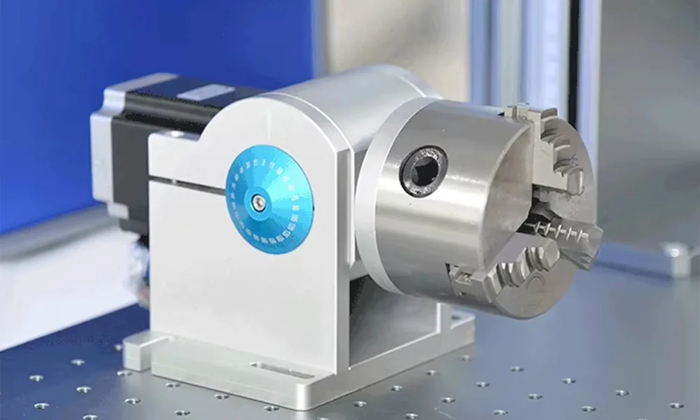
| Round tube or pipe at a fixed station | Use a stable fixture; add controlled rotation when circumference coverage or indexed angular positions are required. | Diameter, runout, seam/feature position, fixture repeatability and required angular coverage. |
| Height or diameter changes between products | Use the appropriate Z/focus strategy for the actual height range. Vision can correct XY position/orientation, but it does not by itself compensate for Z-height variation. | Height range, focus margin, changeover frequency, height sensing or dynamic-focus need, and whether vision is also required. |
| Cut sleeves, short tubes or bundled parts | Manual loading, fixture positioning or vision-assisted positioning depending on tolerance and volume. | Part orientation, fixture datum, operator access, cycle time, batch changeover and error-proofing needs. |
For moving-line projects, review the actual line layout before fixing the marking station. The relative positions of extrusion, cooling, pulling, inspection, cutting, winding and the laser can affect product stability and the available marking window. For motion-control examples, see Flying & Online, Rotary and Vision Positioning.
First-Test Laser Route
Which laser route should be tested first?
The first test should follow the actual surface and target effect, not the industry name alone. Fiber, MOPA fiber, UV and CO2 routes can be useful in different cases, but the actual formulation, coating, color and production speed must still be tested.
| Workpiece / surface condition | First-test direction | Why sample testing is still required |
|---|---|---|
| Bare or coated metal pipe / tube | Start with a fiber route; evaluate MOPA fiber when pulse-control flexibility may help the required surface effect. | Alloy, finish, coating, reflectivity, target contrast/depth and heat effect can change the usable process window. |
| Polymer cable jacket | Screen the actual formulation using the wavelength routes that are technically plausible for that polymer, pigment and target effect, which may include UV, CO2 or a 1064 nm fiber route. | Base polymer alone does not predict the response; colorants, fillers, additives and line speed can change contrast and thermal damage. |
| Heat-shrink tubing | Choose the first route from the real sleeve chemistry and heat sensitivity, then test in the same shrink state used in production. | A mark that looks acceptable before shrinking can distort, fade or damage the sleeve after installation. |
| Plastic tubing | Screen the actual polymer/color combination and target effect before committing to UV, CO2 or fiber-based processing. | Flexible and rigid tubes can differ in formulation, wall thickness, curvature, surface finish and fumes/residue. |
| Painted, coated or printed surface | First define whether the target is color change, controlled coating removal or marking of the underlying substrate, then select the source accordingly. | The active layer may respond differently from the bulk material, and excessive removal can expose or damage the substrate. |
Do not approve a source from a static “best-looking” sample alone. The selected route should also meet the required mark size, production speed, position stability and downstream durability on representative production material.
Failure Modes
Where do wire, cable and tubing laser marking projects fail?
A weak result is easier to diagnose when the visible symptom is linked to material response, focus, motion, data or downstream handling instead of treating every problem as a power issue.
| Observed problem | Likely areas to investigate | How to distinguish the cause |
|---|---|---|
| Contrast is too low | Material formulation, pigment/additive package, wavelength route, energy density and focus. | Compare the same code on representative material while changing one process variable at a time; include different production colors/batches when relevant. |
| Surface melts, chars or foams excessively | Thermal response, excessive local energy, low line speed, focus and pulse strategy. | Compare surface damage and readability as energy delivery and speed are adjusted within a controlled test matrix. |
| Characters stretch or compress as speed changes | Encoder scaling, line-speed reference, trigger timing and flying-mark synchronization. | Measure character length and repeat spacing at minimum, nominal and maximum line speed. |
| Repeat distance drifts | Encoder feedback, product slip, speed reference and trigger logic. | Measure repeated mark positions over a known product length and compare against recorded line motion. |
| Mark moves around the circumference or across the surface | Product wander, rotation, guiding, fixture repeatability or sensor location. | Observe product position at the marking point and separate mechanical movement from scanner positioning error. |
| One side of a code is weak or out of focus | Curvature, diameter change, runout or Z-height variation. | Compare result across the mark width and across the smallest/largest approved diameters. |
| Codes are missing or duplicated after a stop/restart | Trigger state, PLC/data handshake, queue logic, recipe state or restart sequence. | Run controlled pause, stop, restart and product-change tests while logging the expected and actual code sequence. |
| Heat-shrink mark becomes distorted after installation | Marking stage, shrink ratio, heat exposure and insufficient post-shrink validation. | Inspect the same design before and after the real shrink process and verify final readability/position. |
Production Workflow
How does laser marking fit into the production line?
A production system has to control the product, the data and the decision to accept, reject or stop. The exact architecture depends on the line, but the operating sequence should be defined before commissioning.
- Present the productGuide, fixture or convey the wire, cable or tube through a repeatable marking zone.
- Load and validate the active dataApply the correct product recipe, fixed text, lot, reel, serial, meter or other variable information before the marking event is accepted.
- Read motion / triggerUse the agreed line-speed, encoder, sensor or product trigger to determine when and where the mark starts.
- Execute the markRun the proven laser process inside the validated focus, speed and mark-size window.
- Verify where requiredCheck human-readable content or use a reader/vision system when automatic code verification is part of the project.
- Handle failuresDefine alarm, reject, line-stop or operator action for missed triggers, unreadable codes or communication faults.
- Control restart & changeoverConfirm how the system resumes after a pause and how product, batch, reel and recipe changes are authorized.
- Record the resultStore the production or verification data required by the project without assuming every application needs the same traceability architecture.
Sample & Running-Line Acceptance
How should sample and running-line tests be accepted?
Use two separate gates. First prove that the actual material can produce the required mark without unacceptable damage; then prove that the same result remains correct and repeatable under real motion, data and changeover conditions. Acceptance criteria should be agreed before the final configuration is released.
Gate 1 · Sample Feasibility
Can the real material produce an acceptable mark?
- Material result: acceptable contrast or surface effect on representative production material, including important color, coating or batch variants.
- Surface integrity: no unacceptable melting, charring, cracking, excessive removal or functional damage.
- Mark quality: required character height, line width, code size and edge definition are readable under the intended inspection condition.
- Downstream durability: where it can be tested off-line, the mark remains acceptable after representative winding, abrasion, heat, shrinking, installation, cleaning or other required handling.
Gate 2 · Running-Line Acceptance
Does the approved result survive real production conditions?
- Position & interval: longitudinal position, orientation and repeat/meter spacing remain inside the project tolerance.
- Speed window: result remains acceptable at minimum, nominal and maximum production speed, including relevant acceleration or line-state changes.
- Variable data: the correct batch, reel, serial, date or meter value follows the active product recipe and trigger.
- Stop / restart behavior: controlled pause and restart do not create missing, duplicate or mis-positioned marks.
- Reader acceptance: machine-readable codes pass the agreed scanner or vision check under the intended reading condition when automated reading is required.
- Changeover: the approved result can be reproduced across the required diameter, SKU or fixture range without uncontrolled manual adjustment.
For a feasibility review, send representative samples, material/surface information, product diameter or size range, mark artwork or data format, target position, line-speed range or cycle-time target, a short line video/layout, sensor/PLC details and the acceptance checks that matter to your production process.
Final Machine Configuration
How do test results determine the final machine configuration?
The final machine should be a response to the proven process window and line behavior. The test result determines more than laser power: it can change the source, optics, motion control, focus strategy, fixtures, data interfaces, verification and safety/extraction requirements.
| Test result / observation | Configuration decision affected | What should be confirmed before release |
|---|---|---|
| Only one laser route produces the required surface effect without unacceptable damage | Laser source / wavelength route and process window | Result on all representative materials, colors, coatings and required production speeds. |
| Static samples pass but the mark degrades at required line speed | Process window, usable source power, scan strategy, mark size or line requirement | Minimum/nominal/maximum speed test with the final code content and optical setup. |
| Mark position or repeat interval drifts with speed | Encoder, trigger, line synchronization and control logic | Measured position/spacing over the real speed envelope and during speed changes. |
| Diameter or Z variation moves the surface outside the usable focus range | Z adjustment, height sensing, dynamic focus/3D strategy or controlled product presentation | Full height/diameter range and changeover method; vision only where XY/orientation correction is also required. |
| Product rotates, wanders or cannot hold a stable mark position | Guides, fixtures, support, tension control or controlled rotation | Mechanical repeatability at the real marking station before software compensation is relied upon. |
| Circumference or indexed angular marking is required | Rotary axis or other controlled rotation architecture | Diameter range, runout, rotational accuracy, seam/feature reference and cycle-time impact. |
| Small text or 2D code cannot be resolved reliably | Lens/field selection, spot/focus strategy, code size and possibly the marking route | Final field size, working distance, module size and reader acceptance on production geometry. |
| Data changes by reel, batch, serial or upstream system | PLC, MES/database, recipe and communication interface | Data source, handshake, error state, permissions, restart and changeover logic. |
| Automatic verification is needed to detect unreadable or wrong codes | Reader/vision hardware plus reject, alarm or line-stop logic | Acceptance rule, camera/reader position, cycle time and response to a failed read. |
| Process generates smoke, fumes or residue that must be controlled | Extraction or ventilation appropriate to the actual material and process | Representative production material, enclosure/layout, maintenance access and site safety requirements. |
| Many diameters or SKUs must be changed frequently | Recipe control, Z/fixture adjustment, quick-change hardware and operator workflow | Changeover time, error-proofing needs and whether settings can be reproduced without trial-and-error adjustment. |
The machine is ready to specify only after the sample result and production conditions agree. A configuration that makes one good stationary sample is not yet a production solution if line speed, positioning, data handoff, restart behavior or downstream durability remain unproven.
Once the test window is defined, compare the required source, marking field, Z/focus method, online synchronization, rotary/fixture needs and integration options with the available laser marking machine configurations.
FAQ
Wire, cable and tubing laser marking questions
Can wire be marked while it is moving?
Yes, when the marking process is synchronized to the production line and the required code can be completed inside the available speed and mark window. The minimum, nominal and maximum speed should be tested rather than assuming a stationary result will transfer directly to production.
Do heat-shrink tubes need a separate test?
Usually. Test the actual sleeve formulation and the production shrink state because contrast, geometry and readability can change after shrinking and installation.
Do I need a rotary axis for pipe?
Only when the task requires controlled rotation, circumference coverage or indexed angular positions. Straight longitudinal marking on a fixed or moving pipe can use a different handling approach.
Why can the same cable material mark differently?
The base polymer name is only part of the process. Pigments, fillers, additives, coatings, supplier formulation, surface condition and production speed can all move the result into a different process window, so representative samples are important.
Can a vision camera compensate for tube height variation?
Vision is mainly used to locate features and correct XY position or orientation. If the tube surface moves significantly in Z, the system also needs an appropriate focus or height-control strategy for that range.
What should I send for a quote or feasibility test?
Send representative samples, material/surface details, diameter or size range, mark content and dimensions, target position, production speed or cycle time, line video/layout, data/PLC requirements and the acceptance tests the finished mark must pass.
Next Step
Turn the marking requirement into a testable line specification
Provide the workpiece, material/surface, target mark, geometry, production speed and acceptance criteria. Zhuorui can use those inputs to define a sample test, verify the production window and then determine the laser, optics, positioning, motion-control and integration configuration required for the project.