
Industry Application
Energy & Batteries Laser Marking Applications
Plan laser marking for battery cells, modules, packs, solar components and energy connectors where traceability, code readability, surface condition and production handling all affect the final result.
Request a Quote OEM & Custom Inquiry- Cell, module and pack identification
- Solar and energy component marking
- Traceability and online marking planning
Product / Workpiece Scope
Which Energy and Battery Products Need Laser Marking?
Start with the actual workpiece, not the industry name. Battery and energy projects may involve cell-level parts, module and pack components, solar hardware, or power interconnects, and each group introduces different materials, marking areas and production handling.
Lithium Battery Cells and Cell Parts
Cell cans, cell housings, tabs, insulating films and compact identification areas where code size, surface condition, protected zones and heat sensitivity must be checked on real parts.
View lithium battery markingBattery Modules and Packs
Module housings, pack covers, trays, labels and serial-code areas where marking may need to remain linked to assembly, inspection and pack-level production records.
View module and pack markingSolar and Energy Components
Solar frames, junction boxes, nameplates and related energy-component housings where material finish, outdoor exposure, available mark area and readable identification affect acceptance.
View solar component markingBusbars, Terminals and Energy Connectors
High-voltage connectors, copper busbars, terminals, connector shells and plastic housings where one assembly can combine reflective metals, coatings and polymers.
View energy connector marking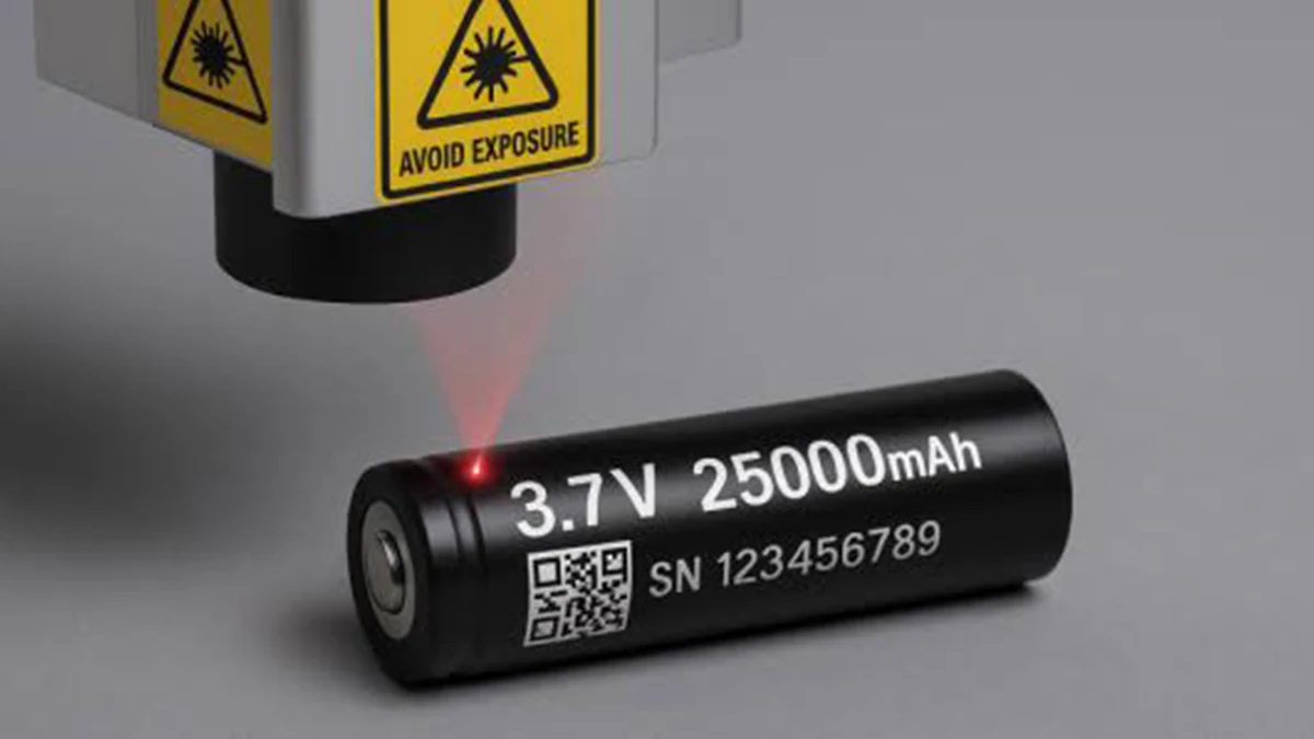
Marked Battery Identification
A battery mark may combine human-readable specifications, a serial number and a machine-readable code inside a limited marking area, so content and readability should be defined together.
Why Mark
Why Are Energy and Battery Components Laser Marked?
The marking task normally begins with identification or production control, not with a laser model. Define why the mark exists before deciding what must be printed or which process should be tested.
Part and Batch Traceability
Serial numbers, lot codes and machine-readable IDs can keep cells, modules, packs or energy components connected to manufacturing and inspection records.
Assembly and Production Control
Variable production data can identify the correct work order, process stage or component relationship and support later scan or data checks.
Product Identification and Safety Information
Model data, polarity, warnings, specifications and other visible information may need to remain readable after assembly and normal handling.
Inspection, Service and Lifecycle Records
A durable readable ID can help connect a physical component to inspection, rework, service or other records when the project requires that traceability.
What Is Marked
What Information Is Usually Marked on Energy and Battery Components?
Once the purpose is clear, define the actual marking content, the smallest required feature and how the information will be read or verified.
| Marking content | Typical application | What to validate |
|---|---|---|
| Serial number or lot code | Cell, module, pack, frame or component identification | Character size, contrast, placement, surface effect and readability after handling. |
| QR or Data Matrix code | Compact machine-readable ID linked to production, inspection or service records | Code size, module definition, available quiet zone, contrast and reading with the intended scanner or verifier. |
| Safety, polarity or warning mark | Battery module, pack enclosure, connector or power component | Position, legibility and visibility after later assembly. |
| Nameplate or specification mark | Solar frames, junction boxes, energy housings and pack covers | Required contrast, exposure conditions and whether the marked surface itself can tolerate the process. |
| Work-order or variable production data | Production marking linked to a control or traceability system | Data source, correct-part binding, trigger timing, scan confirmation and rework or reject handling. |
Result Variables
What Determines the Laser Marking Result?
An energy-industry label such as “battery” does not determine the laser process. The result is controlled by the actual material and surface, the required mark, the available marking area, workpiece geometry and the way the part moves through production.
- Material and surface conditionIdentify the actual substrate, alloy or polymer, then record anodizing, plating, paint, coating, film construction, color, finish and normal batch variation.
- Mark content and feature sizeDefine the smallest character, line width, Data Matrix or QR size, information density and the available marking area.
- Required mark effectHigh contrast, shallow engraving, coating change or removal, visible identification and machine-readable coding are different process goals.
- Geometry and marking positionFlat, cylindrical, curved, recessed, height-varying or assembled surfaces change focus control, fixture design and access to the mark area.
- Protected surfaces and heat sensitivityThin films, polymer housings, coatings, insulation and nearby functional areas may limit acceptable heat input or surface removal.
- Production and verification requirementPart presentation, takt, batch size, scanner use, variable data, PLC/MES connection and reject logic can matter as much as the laser exposure itself.
Common in cell cases, housings, frames, plates and pack structures. Confirm the actual finish; use aluminum laser marking guidance together with the relevant coating page when the surface is treated.
Common in busbars, terminals, connector contacts and other conductive parts. Review copper laser marking for reflectivity and surface-response considerations, then qualify the real alloy and finish.
May appear in cell cans, structural parts, covers and nameplate areas. Start with stainless steel laser marking, then include the actual plating or coating condition in the sample test.
Connector bodies, insulation, labels, junction boxes and protective parts may use polymers or layered surfaces. Check plastics & polymers or the relevant coating route, such as anodized aluminum laser marking, only after the actual material stack is identified.
Sample testing should use the actual material batch and surface finish whenever possible. Two parts described by the same base material can behave differently after coating, plating, anodizing, oxidation or supplier changes.
Target Result
What Marking Result Should Be Defined Before Testing?
“Permanent mark” is too broad to qualify a process. A useful test starts with visible acceptance criteria that can be checked on the real workpiece and, where needed, through the complete production cycle.
- Human-readable identificationRequired text, symbols or warnings remain legible at the intended viewing distance and after normal handling.
- Machine-readable code qualityThe actual QR or Data Matrix can be read with the intended scanner, lighting and production presentation.
- Required contrast, depth or surface effectDefine whether the process needs visible contrast, shallow engraving, coating modification or another specific surface result.
- Part and surface integrityThe accepted mark must not create unacceptable damage to protected coatings, films, insulation, thin sections or nearby functional areas.
- Position repeatabilityThe mark stays inside the permitted area over repeated loading, normal part variation and real fixture or line conditions.
- Required durabilityWhere the application requires it, define relevant handling, abrasion, cleaning, heat, solvent or outdoor exposure before testing.
- Production repeatabilityThe accepted appearance and code quality can be reproduced over representative parts rather than on one demonstration sample.
- Full-cycle taktJudge the complete load, locate, data, mark, verify and unload cycle instead of laser scan time alone.
Geometry & Handling
How Do Part Geometry, Positioning and Loading Affect the Marking Process?
Geometry and handling should first be defined as process constraints. They become equipment decisions only after the marking route and acceptance criteria are proven on representative parts.
Define marking area, datum, orientation, height tolerance and working access. The question is whether the part can return to one repeatable reference over normal production variation.
Record diameter or radius, angular coverage, height difference, recess depth and accessible working distance. These measurements show whether one fixed focal condition is enough.
Define clearance, datum repeatability and the allowed surface or thermal change so a visually good mark is not qualified at the expense of an adjacent functional area.
Define orientation control, locating features, part pitch, transfer speed, changeover and variant handling. These conditions determine real positioning repeatability and the non-laser time inside takt.
Fixture refinement, rotary motion, vision positioning, focus-axis control or 3D marking may become relevant later, but they should solve a measured geometry or positioning problem rather than be selected in advance.
First-Test Laser Route
Which Laser Route Should Be Tested First?
Choose the first test from the actual substrate, surface condition, required effect, feature size and heat sensitivity. The purpose of the first test is to narrow the process route, not to finalize the machine before the samples are qualified.
| Laser route | When it is a reasonable first evaluation | What the sample must prove |
|---|---|---|
| Conventional pulsed fiber | Many metal cell cases, pack covers, frames, plates, stainless-steel parts and selected aluminum or copper components | Required contrast or depth, surface integrity, readable feature size and a stable process window on the actual finish. |
| MOPA fiber | Metal or coated-metal tasks where additional pulse-control flexibility may help widen the acceptable process window or control the surface effect | That the added pulse flexibility produces a measurable acceptance advantage on the real part rather than only a different appearance on a demonstration sample. |
| UV laser | Heat-sensitive plastics, polymer films, small characters and selected coated surfaces where thermal damage or edge quality is a concern | Readable contrast or feature quality while keeping the accepted polymer, coating or nearby protected area within the project limits. |
Other wavelength routes should be evaluated only when the actual material, target effect and available equipment justify that comparison. Do not select a laser only from the words “battery,” “copper” or “plastic”; validate the actual workpiece and finish.
Failure Modes
Where Can Energy and Battery Laser Marking Fail?
A failed sample does not automatically mean the laser lacks power. Separate the observed symptom from possible material, focus, parameter, geometry, verification and handling causes before changing the machine concept.
| Observed problem | Possible causes to distinguish | What to check next |
|---|---|---|
| Code is visible but scan reliability is poor | Low contrast, weak edge definition, code too small, insufficient quiet zone, curved presentation, contamination, scanner or lighting mismatch | Test the final code size with the intended reader and production presentation, not only by visual inspection. |
| Contrast changes between nominally similar parts | Material batch, finish, coating thickness, oxidation, cleaning state, focus variation or narrow process settings | Record surface condition and compare representative parts while holding the inspection method constant. |
| Polymer, film or coating is damaged | Unsuitable wavelength, excessive local energy, heat accumulation, repeated overlap, thin layer construction or limited protected-area clearance | Reduce the problem to material response versus parameter window before deciding that more power or faster marking is required. |
| Copper or another reflective metal gives an unstable result | Actual alloy and finish, oxidation state, focus, pulse behavior, contamination or a process window that is too narrow | Compare controlled settings on the real material and evaluate repeatability, not a single best-looking sample. |
| Mark position drifts across repeated loading | Part datum variation, fixture repeatability, orientation change, height variation or operator placement | Measure the positioning error separately from the laser mark quality, then determine whether the fixture or location method must change. |
| Sample quality is acceptable but takt is missed | Loading, positioning, data transfer, triggering, verification, unloading or rework logic rather than laser scan time alone | Time the full cycle by step before increasing laser power or changing the source. |
| Correct mark quality is produced with the wrong serial or on the wrong part | Recipe selection, data binding, part identification, PLC/MES handshake, scanner feedback or reject handling | Validate the data and error-proofing sequence as part of the production workflow, not as a separate afterthought. |
Production Workflow
What Must the Production Marking Workflow Include?
After the sample process is technically feasible, the production workflow must make the correct part, position, data and acceptance decision repeatable. The laser exposure is only one step in that cycle.
- Load or Present the PartBring the cell, module, pack part, connector or energy component into a repeatable marking position.
- Identify the Part or Work OrderConfirm the correct product variant, recipe and production record before marking.
- Locate the Marking AreaUse the approved datum, fixture or positioning method and confirm required working distance.
- Retrieve or Generate Marking DataPrepare the correct fixed and variable text, serial number, QR or Data Matrix content.
- Apply the Approved ProcessRun the validated laser route and parameter window for that material, surface and mark requirement.
- Read or Inspect the MarkUse the required human, scanner, verifier or vision check rather than appearance alone when machine readability matters.
- Confirm Data BindingWhere traceability is required, confirm that the physical mark matches the intended record or production transaction.
- Accept, Reject or ReworkDefine what happens when code quality, position, data or surface condition fails the approved criteria.
- Unload and Record the CycleComplete the part transfer and record the information required for repeatability, takt or traceability.
If the project requires scanner feedback, PLC signals or MES data exchange, review the traceability and data integration workflow after the marking and acceptance requirements are defined.
Sample Qualification
How Should Representative Energy and Battery Samples Be Qualified?
Qualification should prove more than “the laser can make a mark.” It should show that the selected process can meet the defined result on representative parts and can be repeated with the intended inspection and handling method.
- Use Representative PartsTest the actual material, coating, finish, geometry and normal production variation whenever possible.
- Use Real Marking ContentTest the actual smallest text, code density, line width and marking area instead of only a large logo or easy demonstration pattern.
- Build a Controlled Process MatrixChange the necessary laser variables while keeping the sample condition, focus, fixture and inspection method controlled.
- Inspect the Mark and Protected AreasJudge contrast, depth or surface effect together with any coating, insulation or nearby functional area that must remain acceptable.
- Verify Machine-Readable CodesUse the intended scanner, verifier or production reading method when code quality is part of acceptance.
- Run Required Exposure ChecksWhere the project requires abrasion, cleaning, heat, solvent or outdoor exposure, apply the relevant check before approving durability.
- Repeat Across Multiple PartsConfirm the accepted result can be reproduced over representative parts rather than relying on one best sample.
- Test the Full Production CycleMeasure loading, locating, data handling, marking, verification, reject logic and unloading when takt or automation matters.
- Record the Accepted Process WindowKeep the approved settings, part condition, inspection method, failures and limits so final machine configuration is based on evidence.
Final Machine Configuration
How Do Sample-Test Results Determine the Final Machine Configuration?
The machine should be configured from the qualified process and measured production constraints. Use the test result to justify the laser source, optics, positioning, handling, verification and integration instead of choosing those features from industry name alone.
| Qualified test or production result | What it means | Configuration decision to evaluate |
|---|---|---|
| Conventional fiber meets the required mark quality with a repeatable process window | The basic fiber route is technically suitable for the tested part | Finalize the appropriate fiber laser marking source and power range from the actual sample result rather than adding unnecessary process complexity. |
| MOPA fiber provides a measurably better acceptable window on the actual metal or coating | Additional pulse-control flexibility has practical value for this workpiece | Specify a MOPA fiber configuration only when that advantage is repeatable and relevant to the acceptance criteria. |
| UV is the route that meets the polymer, film or coating acceptance criteria | The heat-sensitive or fine-feature task benefits from the tested UV process | Finalize the appropriate UV laser marking configuration around the validated mark size, field and working distance. |
| Small characters or code cells must fit inside a defined marking field | Feature size and field size must be balanced together | Set the field lens, optics, marking field and working distance from the qualified feature size and usable field rather than from field size alone. |
| The qualified workpiece envelope or loading path exceeds a compact workstation | Part size and physical access become machine-layout constraints | Set the usable table area, enclosure opening, Z travel, working clearance and loading direction from the real workpiece envelope; evaluate a larger motion or open-workpiece configuration only when those measured dimensions require it. |
| Height variation or curved geometry cannot stay inside one stable focal condition | A fixed focal plane is not enough for the approved mark area | Evaluate focus-axis control, 3D curved-surface marking or rotary motion according to the actual geometry and required coverage. |
| Fixture-only positioning cannot hold the required mark location over repeated loading | The positioning method, not the laser mark itself, is the limiting factor | Refine the fixture or evaluate vision positioning when the measured position error justifies it. |
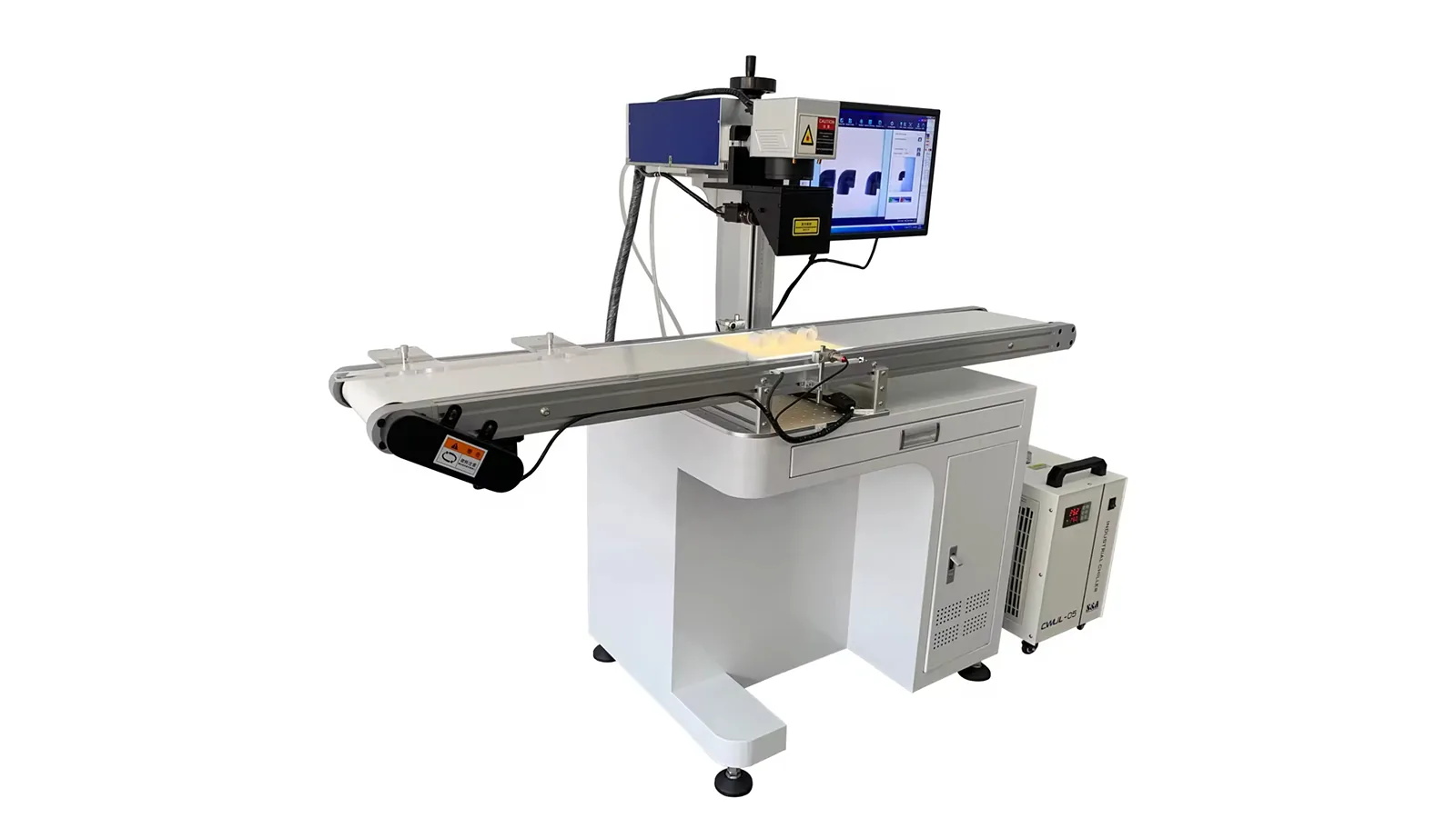
| A conveyor or continuously moving part must be marked inside a defined timing window | Motion synchronization becomes part of the process requirement | Evaluate a flying laser marking machine and the online marking workflow after trigger, speed and mark-window requirements are measured. |
| Laser quality is acceptable but manual loading, verification or unloading misses takt | The production bottleneck is outside the laser exposure | Evaluate multi-station handling, fixtures or automatic marking based on the measured cycle breakdown instead of increasing laser power by default. |
| Every marked part must be linked to serial data, scan confirmation or MES records | The marking head must operate inside a closed information loop | Add the required scanner, PLC and traceability data integration scope, including defined reject or rework behavior. |
| The accepted process produces fumes, particles or debris that must be controlled | Process by-products affect workstation design and maintenance | Include the required extraction, enclosure and workstation review as part of the final system configuration. |
A quotation is most useful after these links are clear: actual material and surface → target mark → geometry and loading → first-test laser → qualified acceptance result → production cycle → final machine configuration.
FAQ
Common Questions About Energy and Battery Laser Marking
Can one laser mark every material in a battery pack?
Not necessarily. A pack can combine aluminum, copper, stainless steel, plated or coated surfaces, polymers and labels. The same laser route may not produce the required contrast, surface integrity or code quality on every material and finish.
How should machine-readable code quality be accepted?
Use the intended production scanner, verifier or inspection method on the final code size and workpiece presentation. Visual appearance alone is not enough when a QR or Data Matrix code is part of the requirement.
What should I prepare before asking for a sample test or quote?
Prepare product photos or drawings, exact material and surface information, marking content and size, target result, sample parts, workpiece dimensions, expected production rate, loading method, scanner or MES requirements, and any protected areas or durability conditions.
Next Steps
Turn Your Energy or Battery Marking Task Into a Testable Requirement
Send the actual component, material and surface condition, marking content, target result, geometry, production rate and samples when possible. Zhuorui Laser can use the sample-test result to narrow the laser route and define the required optics, positioning, verification, handling and integration scope.
Prepare for review: component type · material and coating · product photos or drawings · mark content and size · target result · code reading method · geometry and loading · production rate · line or data needs · sample quantity.