
Plated Surface Guide
Plated Metal Laser Marking
Laser marking on plated metal is an interlayer-control problem, not a bare-metal problem. Nickel, chrome and gold surfaces may be single layers, flash layers or multilayer stacks over steel, copper, brass, stainless steel or another base. The accepted mark must state which layer may change, which layer must remain intact and how adhesion, corrosion, electrical function and appearance will be checked.
- Nickel, chrome, gold and multilayer plating must be tested as a stack, not treated like bare metal.
- Primary risk: breakthrough, interface lift, exposed substrate and changed corrosion or electrical function.
- Best practice: define the permitted stopping layer, acceptance checks and finished-part sample before machine selection.
Quick Answer
Can Plated Metal Be Laser Marked?
Yes. Nickel-plated, chrome-plated, gold-plated and other plated metal parts can be laser marked, but the acceptable process depends on the complete plating stack, layer thickness, substrate, surface condition and the layer that is allowed to change or be exposed.
A plated part can look like one metal while the laser sees a thin finish over a barrier, underplate and base. If the beam removes too much of the top layer, it can expose the next layer, disturb the interface or reach a substrate whose reflectivity, corrosion behavior or electrical function is different.
Before a source is selected, record the visible finish, plating sequence, nominal and local thickness, hardness or porosity information when available, base metal, pretreatment, geometry and the permitted stopping layer. Then define whether the target is a controlled surface change, a mark contained within the finish, a window to an approved underlayer or a code that intentionally reaches the substrate.
The key question is not only whether the surface marks: it is whether the laser can create the required contrast or removal while stopping at the correct layer and preserving adhesion, corrosion protection, electrical function and appearance.

Plating Stack
What Determines Laser Marking Results on Plated Metal?
“Nickel-plated,” “chrome-plated” and “gold-plated” are starting labels, not complete process specifications. The same visible finish can sit over different underplates, substrates, thickness distributions and service requirements.
Top Layer and Flash
Record whether the visible layer is decorative chrome, hard chrome, nickel, gold flash or a thicker gold finish. Color, reflectivity, hardness, ductility and local thickness influence the first interaction.
Decorative chrome is often a thin, bright finish over nickel; hard chrome can be thicker and more wear-oriented. Gold flash is soft and thin, so a visually clean pass can still scratch, lose valuable material or reveal the underplate.
Barrier and Intermediate Layers
Nickel barriers, copper underplates, strike layers and other intermediates can have different absorption, hardness, ductility, porosity and corrosion roles.
Breaking through the visible layer can expose an intermediate layer that is visually acceptable but functionally, electrically or corrosion-wise unacceptable.
Substrate and Preparation
Steel, stainless steel, brass, copper, aluminum and zinc-based substrates spread heat and reflect the beam differently after the plating opens.
Record polishing, roughness, pretreatment, casting or machining marks and any pre-existing pits or pores.
Function and Exposure
Electrical contact, solderability, friction, wear, corrosion barrier, appearance and cleanability can all set a different stopping boundary.
The layer that gives the best visual contrast is not automatically the layer that meets the part requirement.
Chrome: Decorative vs Hard
Confirm whether the bright chrome is decorative over a nickel barrier or hard chrome selected for wear. Their thickness, microcracking, reflectivity and acceptable breakthrough boundary can differ materially.
Inspect edge lift, exposed nickel, roughness and corrosion path after cleaning and handling.
Nickel: Barrier and Underplate
Nickel may be the visible finish, a barrier under chrome or an intermediate layer over copper and steel. Local thickness and adhesion determine whether a darker mark is a finish change or an unintended opening.
Compare the result with the solid nickel material route only after the plated stack is identified.
Gold: Flash, Loss and Appearance
Gold flash and thicker decorative gold respond differently to heat and removal. Soft surfaces can scratch under fixturing; particles should be collected and recovered where required.
Define permitted gold loss, post-polishing or cleaning, viewing distance and the appearance acceptance standard before testing. See the solid gold material route for adjacent behavior.
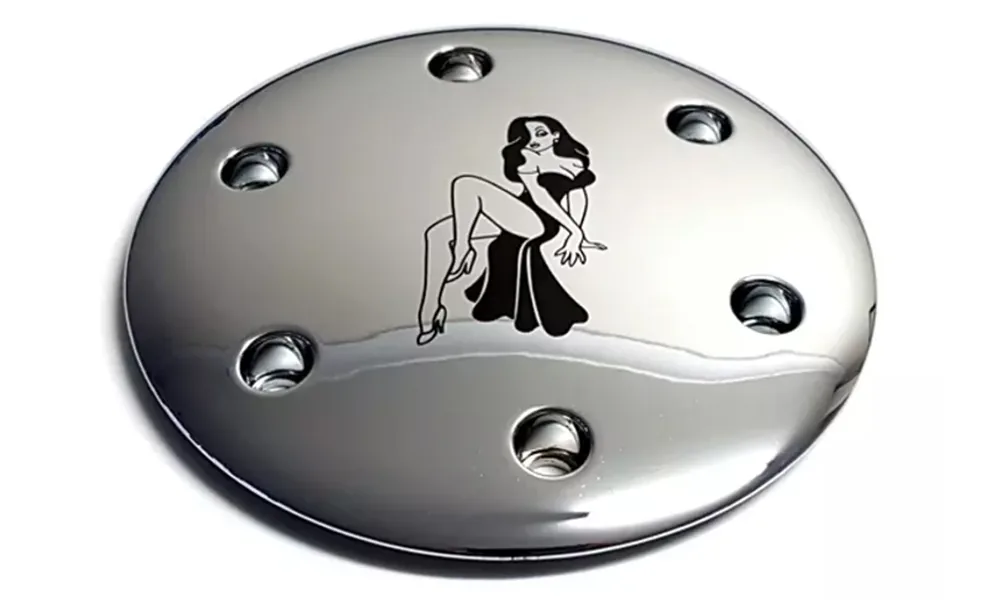
Plated-Metal Marking Examples
These examples show why plated surfaces should be evaluated as a layer system rather than by appearance alone. The visible mark does not reveal the full plating sequence, local thickness or permitted stopping layer, so final settings still need to be confirmed on the finished part.


Related coating routes
Use the closest surface route when the part is actually painted metal, powder-coated metal or anodized aluminum. Their layer mechanisms and stopping limits are different.
Related substrate routes
If the approved process intentionally marks the exposed base, compare the relevant steel, stainless steel or copper guidance after the plated-stack test. Other substrates should be routed through the metals hub.
Typical Applications
Where Are Plated Metal Parts Used and Why Are They Marked?
Plating is often chosen for corrosion resistance, electrical performance, wear behavior or appearance. Laser marking is then used to add identification or traceability without adding an ink or label, but the mark must not compromise the function the plating was selected to provide.
Electrical Connectors and Contacts
Nickel, gold or other plated contact parts may need part numbers, polarity, cavity identification, lot codes or traceability marks.
The main constraint is keeping the approved contact or barrier layer intact wherever electrical performance, solderability or corrosion resistance depends on it.
Decorative Hardware and Fittings
Chrome- or nickel-plated handles, fittings, trim and hardware may need logos, model identification, serials or batch information.
Appearance usually matters as much as contrast, so halo, scratching, roughness, exposed underplate and batch-to-batch color change need explicit acceptance limits.
Industrial Fasteners and Hardware
Plated screws, fittings, clips and hardware may be marked for grade, size, lot, assembly identification or service traceability.
Edges, small radii and locally different plating thickness can narrow the process window compared with a flat coupon.
Electronic and Precision Components
Plated housings, terminals, shields and small precision components may require orientation marks, internal identification, serials or machine-readable codes.
Fine features, reflective surfaces, restricted marking zones and nearby functional surfaces can make focus, fixture and inspection requirements more demanding.
Why application matters: the same plating stack can have a very different acceptance boundary on a decorative fitting, an electrical contact or a traceability component. Define what the plating is doing before deciding what the laser is allowed to change.
Mark Content
What Is Usually Marked on Plated Metal Parts?
The artwork itself may be simple, but its smallest feature, contrast requirement and verification method directly affect the process window and machine configuration.
Identification
Part number, model, serial number, date code, lot or batch information used to distinguish the component or production record.
Traceability Codes
Data Matrix, QR code or other production identifiers where module size, quiet zone, lighting and reader or verifier method must be defined before acceptance.
Functional Information
Polarity, terminal position, cavity number, orientation, inspection status or other information that helps assembly, testing or service.
Branding and Appearance
Logo, brand name, decorative text or visible serials where edge quality, gloss, halo, color consistency and scratch resistance may be part of the acceptance standard.
Mark content and mark mechanism are different decisions: a serial number or code can be produced by a finish change, controlled underlayer exposure or base-metal exposure. The required content does not by itself define the acceptable layer change.
Mark Outcomes
What Marking Result Should You Target?
On plated metal, “marking” can mean changing the visible finish, exposing an underlayer or reaching the base. Each route needs a different inspection plan because contrast, adhesion and service function can move in opposite directions.
| Target outcome | What may change | Main interlayer risk | Validate on the final part |
|---|---|---|---|
| Controlled change within the finish | Reflectance, color or texture changes while the plating remains functionally closed. | Local thinning, heat tint, roughness, gloss halo or hidden adhesion change. | Contrast under real lighting, tactile feel, thickness loss, adhesion and wear/chemical exposure. |
| Expose a defined underlayer | The top layer is removed to reveal nickel, copper or another approved intermediate layer. | Partial breakthrough, feathered edge, interface lift, porosity or an exposed layer that does not meet electrical/corrosion needs. | Stopping-layer identity, edge width, cleanliness, exposed area, adhesion around the mark and function. |
| Expose the base metal | The plating stack is opened to the steel, brass, copper, stainless or other substrate. | Substrate reflection, heat tint, burr, galvanic/corrosion risk and loss of the protective barrier. | Depth, roughness, corrosion condition, post-cleaning appearance and downstream protection. |
| Machine-readable code | Fine lines or a controlled window create contrast between layers. | Reflective glare, layer thickness variation, residue, curvature and unstable edge position can reduce reading or verification quality. | Reader or verifier result using the specified lighting, module size, quiet zone, grade method and reject rule. |
| Decorative logo or serial | A visible change is created on a premium or cosmetic plated surface. | Color mismatch, visible halo, local pitting, scratch-like texture or batch-to-batch finish variation. | Viewing distance, lighting, cleaning, scratch resistance, appearance standard and repeatability. |
Do not use a visually attractive breakthrough as the acceptance rule: a mark can look clean while exposing the wrong layer, reducing a corrosion barrier, changing electrical contact behavior or weakening an interface. Agree the stopping layer and the functional inspection before testing.
Geometry and Thickness
How Do Plating Thickness, Part Shape and Size Change the Process?
The plating thickness usually sets the most important layer boundary, while part shape, overall thickness and size determine how consistently that boundary can be held across the real workpiece.
Plating Thickness
A thin flash layer and a thicker wear-oriented deposit do not offer the same stopping window. When the permitted exposure is narrow, even a small change in removed depth can change which layer is visible.
Local Thickness Variation
Edges, holes, recesses and plating build-up can differ from broad flat areas. A setting that is incomplete on one zone can already be breaking through another, so representative locations should be included in the sample test.
Curvature and Height Variation
Rings, tubes, shafts, domed surfaces and stepped parts move the surface away from the nominal focal plane. Spot size and energy density can change enough to affect contrast, edge width and layer selectivity.
Overall Part Thickness and Thermal Mass
Overall thickness is not the same as plating thickness. On very small, thin or heat-sensitive components, the part can accumulate heat more quickly; larger thermal mass may spread heat differently during repeated passes.
Part Size and Marking Field
Large parts or widely separated marks may require a larger field, repositioning or motion. Field size, lens choice and working distance also affect spot size, focal tolerance and energy density.
Edges, Holes and Functional Zones
Marking close to an edge, seal surface, contact pad or corrosion-critical area can require a tighter boundary than marking the middle of a cosmetic panel. Record zones where any plating exposure is prohibited.
Do not qualify the process on one convenient flat area: the real test set should include the thinnest or thickest known plating zones, curved or height-varying features, edges and any function-critical areas that could become the production limit.
Laser Direction
Screen a Source Against the Stack, Not the Finish Name
A 1064 nm fiber laser marking machine is often a practical first route to screen on plated metal, but a bright nickel, chrome or gold surface can reflect strongly and the response may change when a lower layer opens.
Compare peak power and average power separately, then record pulse duration, pulse energy, repetition rate, scan speed, hatch spacing, pass count and focus while holding the artwork and inspection method constant. Spot size, field lens and working distance change energy density; focal depth, field position and allowable focal tolerance change whether the process stays inside the intended layer across the part. MOPA control can help map a narrower boundary, but it does not guarantee clean removal or lower substrate heat. UV or another wavelength may be worth screening for fine layer changes or a heat-sensitive finish; CO2 is a conditional route for selected non-metallic layers and must be checked against the exposed metal.
Optical screening record: tie peak/average power, spot size, lens/working distance, focal depth, field position and focal tolerance to breakthrough observations. If a stopping-layer window collapses at the edge of the field or with small height changes, record that as a process boundary rather than compensating with more energy.
After the optical process is proven, the accepted mark area, part geometry, loading method, focus tolerance, inspection method and production rate can be translated into the complete machine configuration.

| Route | Worth screening when | Boundary | Verify |
|---|---|---|---|
| 1064 nm fiber | Layer contrast, controlled removal or a defined finish change is required on a compatible stack. | Reflectivity, plating thickness and the newly exposed layer can change absorption and heat abruptly. | Stopping-layer control, edge, residue, reflection, exposed area, substrate condition and repeatability. |
| MOPA fiber | Pulse-duration and repetition-rate control may help compare a narrow interface or cosmetic boundary. | More control does not guarantee lower heat, no lift or a stable window across thickness variation. | Pulse behavior, overlap, focus, interface condition, layer identity, code result and fume load. |
| UV | Fine detail, coating absorption or a limited heat-spread requirement justifies a separate trial. | UV is not damage-free; debris, throughput, layer adhesion and exposed-metal response remain sample-dependent. | Feature fidelity, layer selectivity, residue, edge width, heat effect and repeatability. |
| CO2 or other route | A non-metallic layer or special finish shows a useful response at another wavelength. | The metal stack may reflect or redirect energy; beam delivery and complete-machine configuration must be confirmed. | Removal mechanism, exposed layer, edge, debris, safety controls and production repeatability. |
Interlayer Risk
Read the Failure Mode Before Increasing Energy
Plated surfaces can fail at the visible mark, at the interface or in the newly exposed substrate. A low-contrast result does not automatically justify more energy; first identify which layer or boundary is moving.
Breakthrough
- Top-layer removal continues into an intermediate layer or base before the target boundary is reached.
- Inspect cross-section or thickness proxy when the allowed exposure is narrow.
- Separate incomplete removal from over-removal; they need different parameter changes.
Interface Lift
- Heat, pulse overlap, contamination or weak adhesion can create a lifted edge or delamination around the mark.
- Check after cleaning and handling, not only immediately after the pass.
- Record whether lift is cosmetic, functional or a barrier failure.
Porosity and Pits
- Pores, pits and local thickness variation can trap residue or produce uneven exposure.
- Compare representative areas, edges and lots rather than one polished coupon.
- Use cleaning and microscopy rules that match the real component.
Substrate Reflection
- Once a reflective base is exposed, beam return and heat flow can change sharply.
- Review direct, specular and diffuse reflection paths, fixture orientation, enclosure and guarding for the complete system.
- Do not infer a production-safe setup from a source label alone.
Safety and chemistry boundary: 1064 nm fiber radiation is invisible, and polished plated parts can create direct, specular and diffuse reflections. For an open setup or Class 4 laser work area, define controlled access, complete enclosure or guarding, a safety-rated circuit, door interlocks, emergency stop and automated abnormal-stop behavior before repeated work. Plating, cleaning chemistry, oils and residues may alter fumes or particles; review the part and process SDS, local extraction, filtration, waste handling and site risk assessment. Exposure limits and the final machine safety design must be verified for the complete system and operating site.
Sample Test Checklist
How Should a Plated-Metal Sample Be Tested and Evaluated?
One bright coupon cannot prove a plated-metal process. The sample review should expose thickness variation, interface condition, base reflectivity, cleaning, durability and the production inspection method that will govern release.
Stack and Geometry
- Plating: visible finish, underplate sequence, supplier/process, nominal thickness and local variation if known.
- Base: steel, stainless, brass, copper, aluminum or another substrate; roughness, pretreatment and polish.
- Part: flatness, curvature, edge distance, holes, contact zones and areas where exposure is prohibited.
Mark and Acceptance
- Target: finish change, controlled underlayer exposure, base exposure, logo, serial or code.
- Boundary: permitted layer, maximum depth, line width, edge position, roughness and residue.
- Inspection: reader or verifier method, lighting, module size, visual standard, adhesion, electrical or corrosion check.
Durability and Production
- Exposure: solvents, friction, humidity, salt, heat, outdoor service or downstream finishing.
- Workflow: batch size, datum, loading, inspection, variable data, line speed and reject handling.
- Safety: plating/cleaning SDS, extraction, filtration, enclosure, waste and site constraints.
| Review output | What it can include | Boundary |
|---|---|---|
| Stack-specific screening record | Routes and parameter windows evaluated, focus/scan assumptions, layer boundary and a documented no-go result when no acceptable window is found. | The result is specific to the supplied plating stack and is not a universal recipe for all nickel, chrome or gold parts. |
| Layer and surface evidence | Before/after images and observations for finish change, breakthrough, edge, lift, residue, exposed layer and cleaning state. | Visual evidence does not replace adhesion, electrical, corrosion, wear or downstream-process checks. |
| Code or measurement result | Dimensional checks, reader results and, when scoped, verifier grade using the agreed method and lighting. | A reader pass is not a verifier grade, product approval or regulatory statement. |
| Production handoff | Observed marking time plus fixture, extraction, handling, inspection and data assumptions for the next system review. | Laboratory marking time is not a guaranteed line cycle until the complete workflow and safety sequence are validated. |
Include controls: send unmarked parts, representative lots and any known plating-thickness map. A single polished sample can hide pores, edge build, local thin spots or an interface condition that changes the accepted process.
Machine Configuration
How Is the Final Machine Configuration Chosen?
The sample test should first identify a stable optical route and acceptable stopping window. The final machine is then configured around the real mark area, part geometry, focus tolerance, handling method, inspection requirement, extraction need and production rate.
| Verified requirement | Configuration decision it affects | What to confirm before quotation |
|---|---|---|
| Accepted fiber, MOPA fiber or UV process window | Laser source family and pulse-control requirement. | Target result, permitted stopping layer, acceptable parameter window and repeatability on representative parts. |
| Mark size and available working area | Field lens, marking field, working distance and whether repositioning or motion is needed. | Largest artwork, smallest feature, location tolerance and usable clearance around the part. |
| Cylinder, ring, shaft or curved surface | Rotary axis, fixture, multi-position indexing or 3D focus strategy. | Part diameter, marked arc, height variation, datum and whether the mark must wrap around the surface. |
| Variable part position or orientation | Vision, datum tooling or custom fixture requirement. | Part-to-part positional variation, allowable mark-location error and whether the code or artwork is variable. |
| Code reading or verification requirement | Reader, camera, lighting and reject-handling strategy. | Code type, module size, required inspection method, lighting condition and pass/fail rule. |
| Residue, fumes or removed plating | Extraction, filtration, enclosure and maintenance access. | Plating/cleaning chemistry, SDS information, debris behavior and site extraction constraints. |
| Batch or line production | Manual loading, fixture count, rotary, conveyor, automation, I/O and safeguarding level. | Batch size, takt target, loading sequence, reject handling, operator access, utilities and destination requirements. |
Configuration should follow the sample result, not precede it: the verified marking window determines the optical route; part geometry and production workflow determine the fixture, motion, vision, enclosure, extraction and automation needed around that route.
FAQ
Plated Metal Laser Marking Questions
Can nickel-plated, chrome-plated and gold-plated metal be laser marked?
They can be screened, but the visible finish alone is not enough to select a process. Plating sequence, thickness, substrate, reflectivity, adhesion, porosity and the permitted stopping layer determine whether a finish change, underlayer window or base mark is acceptable.
Does the laser always remove the plating?
No. A trial may target a controlled finish change, a defined underlayer exposure or a base-metal mark. The intended layer and the maximum allowed exposure should be written into the acceptance record before testing.
Can a clean-looking mark weaken the part?
Yes. Breakthrough can reduce a barrier, expose a galvanically sensitive substrate, change contact behavior or create an interface defect that is not visible immediately. Inspect the layer identity, adhesion and service requirement after cleaning and handling.
Which laser is used for plated metal?
A 1064 nm fiber source is often a first screening direction, with MOPA pulse control, UV or another route considered when the exact stack and feature requirement justify it. No wavelength or wattage is a universal answer; sample evidence should decide.
Why can two nickel-plated or chrome-plated parts need different laser settings?
The visible finish may be the same while plating thickness, underplate, substrate, polish, porosity, curvature, thermal mass and permitted stopping layer are different. Parameters should therefore be qualified on representative finished parts rather than copied from the finish name alone.
What should I send for a plated-metal sample test?
Send finished parts or representative coupons with visible finish, underplate and base information, plating thickness if known, drawing/artwork, smallest feature, permitted layer exposure, durability/electrical/corrosion requirement, cleaning method and production context.
Sample Review
Start With the Plating Stack and the Stopping Boundary
Share the visible finish, nickel/chrome/gold layer sequence, base metal, target mark, permitted exposure, inspection method, durability or electrical requirement and production context. For a sample-feasibility review, include finished plated parts or representative coupons and ask the team for sample-delivery instructions; attach photos, drawings and the layer record when the request form permits attachments.
Prepare for faster evaluation: plating supplier/process or layer record · finish and thickness · substrate and pretreatment · finished parts or representative coupons · part drawing/photos · mark artwork and smallest feature · permitted stopping layer · electrical/corrosion/wear requirement · reader/verifier method · batch size · fixture/automation · extraction and destination/voltage · sample-delivery instructions.