Fiber vs CO2 Laser Marking: Which Is Right for Your Material?
For direct marking on most bare metal parts, a fiber laser is usually the better starting point. For wood, paper, cardboard, and many leather surfaces, a CO2 laser is generally the more suitable choice. The decision becomes less straightforward with engineered plastics, coated metals, glass, and packaging materials, where the surface formulation and required mark can matter as much as the material name.
The useful question is not simply which laser can leave a visible mark. It is which process can produce the required contrast, readability, surface condition, and consistency on the actual part, within an acceptable production cycle. That distinction should guide the comparison before power ratings or machine prices enter the discussion.
Fiber or CO2: Which Should You Evaluate First?
Start with the surface that the laser will actually contact. If an uncoated stainless steel component needs a serial number or a Data Matrix code, fiber marking is a logical first trial because it can modify or remove metal directly. If the job is date coding on paperboard cartons, CO2 is usually the more appropriate route because the material responds readily to its infrared wavelength.
The choice is less obvious for a colored anodized aluminum nameplate or a molded plastic enclosure. In these cases, the coating, pigment, additives, or surface finish may determine which laser produces an acceptable result.
These distinctions lead to a practical rule: choose the first laser to test from the material’s exposed surface and the required marking effect, not from a broad metal-versus-nonmetal label. A suitable first choice reduces unnecessary trials; it does not replace validation on production-representative parts.
Why Do Fiber and CO2 Lasers Mark Materials Differently?
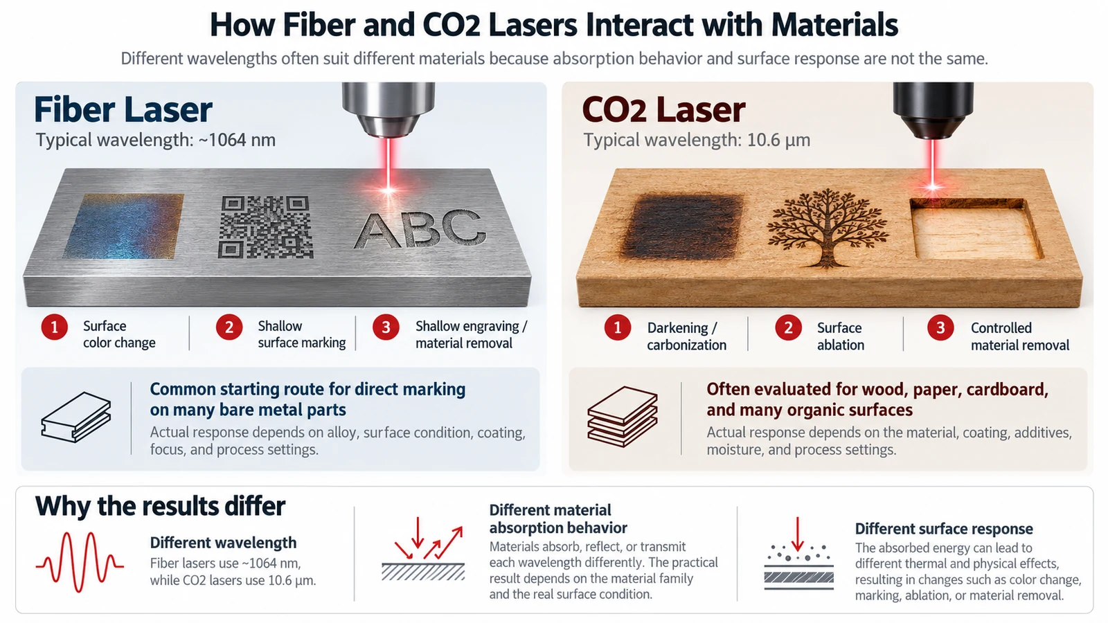
Conventional fiber laser markers commonly operate near 1,064 nanometers, in the near-infrared region. Many industrial CO2 markers operate at 10.6 micrometers, a much longer infrared wavelength, while some systems use alternatives such as 9.3 micrometers for particular substrates. These wavelengths interact differently with metals, polymers, coatings, and organic materials.
Absorbed laser energy can produce several kinds of change: a metal may develop an oxide-based color contrast or lose a small amount of surface material; a polymer may change color, foam, melt, or have a layer removed; an organic surface may darken through localized thermal decomposition. The outcome depends on both material response and delivered energy. Wavelength helps determine what is possible, but it does not by itself establish an acceptable result.
Beam delivery, focusing, pulse behavior, scan settings, and exposure time also matter. Even when the wavelength is suitable, these conditions determine whether the material responds in a controlled way and the mark meets its acceptance criteria.
Which Materials and Marking Results Favor Each Laser?
Material compatibility is best understood as a combination of substrate, surface condition, and required result. A laser that creates strong contrast on one finish may create a weak mark or excessive surface change on another.
Bare Metals: Direct Marks, Contrast, and Engraving
Fiber lasers are generally the first choice for direct marking of uncoated stainless steel, carbon steel, aluminum, titanium, and many other industrial metal parts. Depending on the alloy and process settings, they can create visible color changes, shallow surface marks, or recessed engravings without applying a separate marking compound.
These outcomes are not interchangeable. A dark surface mark may work well for a traceability code when the part must remain relatively smooth. A recessed mark may be required where a specified engraving depth or greater resistance to mechanical wear is part of the acceptance criteria. Achieving depth usually involves more material removal and can increase processing time or change the surface. On bare aluminum, a particular shade of black should not be assumed achievable with every fiber source and finish; contrast must be checked on the actual alloy and surface condition.
A conventional CO2 marker is not normally the practical option for directly engraving bare metal. It may produce a mark on metal with a suitable marking paste, spray, or tape, but that adds preparation and cleaning steps and is a different process from directly modifying the substrate.
Wood, Paper, Cardboard, and Leather: Surface Response Matters
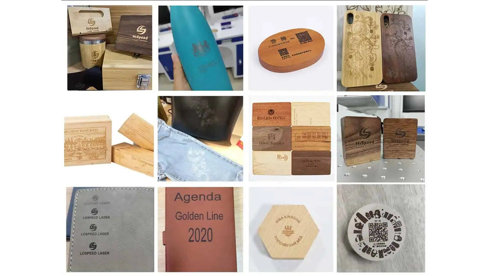
CO2 lasers are generally well matched to wood, paper, cardboard, and many leather surfaces. A visible mark may be created through localized darkening, carbonization, or controlled material removal, depending on the substrate. This makes CO2 a common candidate for packaging codes, product identification, and decorative or functional marks on organic materials.
The challenge is controlling that response. More visible burning is not necessarily a better mark. Excessive energy can produce char, soot, ragged character edges, deformation, or an unacceptable change to a finished surface. Wood grain, paper coatings, leather finishes, color, and moisture can all affect the result.

| Material or surface | Fiber laser | CO2 laser | What needs checking |
|---|---|---|---|
| Bare stainless steel, steel, aluminum, and similar metals | Usually the first choice for direct marking or engraving | Generally not preferred for direct bare-metal marking | Contrast, depth, alloy, finish, and permitted surface change |
| Wood, paper, cardboard, and many leather surfaces | Usually not the first choice | Usually the first choice | Darkening, edge quality, charring, and material damage |
| Engineered plastics | Possible with suitable formulations and marking conditions | Possible with suitable formulations and marking conditions | Resin grade, pigments, additives, color, and deformation |
| Anodized, painted, or otherwise coated metals | May mark or modify the surface layer | May mark or remove certain surface layers | Coating type, layer removal, underlying material, and protection requirements |
| Glass and PET containers | Generally not the usual first route for standard transparent surfaces | A candidate for selected glass and PET marking applications | Wavelength, wall thickness, appearance, and structural integrity |
The table narrows the options, but it cannot resolve the difficult cases by itself. In particular, plastics and coated products require a closer look at which layer absorbs the beam and what the marking process is permitted to change.
When Do Plastics, Coatings, and Transparent Materials Change the Answer?
For these materials, the exposed surface may behave very differently from the base material named on a drawing. The following situations show why an initial recommendation sometimes needs closer evaluation.
Before testing an unfamiliar plastic, synthetic leather, or coated material, confirm its composition and laser-processing safety. PVC and some other halogen-containing materials can release hazardous or corrosive fumes under laser exposure and may be unsuitable for laser processing. Do not trial-mark an unidentified formulation simply to see whether a visible code can be produced; establish material suitability and the necessary fume controls first.

Plastics: Resin Grade, Color, and Additives Matter
“ABS,” “PC,” or “PP” is not enough information to predict a reliable laser mark. The actual formulation may include pigments, fillers, flame retardants, or laser-sensitive additives that change how strongly the part absorbs a given wavelength. Some formulations respond well to near-infrared fiber lasers; others may be more suitable for CO2 processing or require a different wavelength altogether.
The desired marking mechanism matters just as much. A laser might create a dark color change with little visible relief, produce a lighter foamed mark on a darker plastic, or remove a thin surface coating to expose a contrasting layer. Those results have different implications for appearance, texture, and functional surfaces. If the plastic melts, warps, becomes brittle, or loses code definition, a visible mark alone is not evidence of a suitable process.
For a molded housing or connector, a meaningful trial therefore needs the actual resin grade, color, additive package where available, and final surface finish. Testing a generic plastic sample does not establish that another formulation will behave the same way.
Coated Metals: Are You Marking the Coating or the Metal?
Consider a dark anodized aluminum tag. A laser can create a light mark by modifying or removing part of the colored surface layer. Both fiber and CO2 systems can be candidates for certain anodized finishes. But the fact that the part is made from aluminum does not mean the laser has deeply engraved bare aluminum underneath.
Painted or powder-coated parts present a related decision. If the goal is to reveal the base material or a contrasting layer, selective coating removal may provide the right appearance. If the coating serves a corrosion, electrical, or other protective purpose, removing it may be unacceptable even when the code is highly legible. The required outcome must be defined before choosing the process.
Glass, PET, and Thin Packaging: Visible Does Not Always Mean Acceptable
Transparency to visible light does not tell you how a material will respond to a CO2 laser. CO2 markers can produce frosted-looking marks on some glass and PET products, but the mechanism and acceptable process window are different. On glass, localized thermal effects can produce microfractures or surface changes; appearance must be evaluated alongside the risk of chipping or weakening the product.
On PET bottles, even the choice between CO2 wavelengths can matter. Systems operating near 9.3 micrometers may produce a shallower, foamed-looking effect on certain thin-walled PET containers, whereas a 10.6-micrometer process may remove more material. The appropriate choice depends on bottle construction and the required code. A readable date mark is not sufficient if it creates a weak point, pinhole, or other unacceptable change to the packaging.
Thin films and multilayer packaging deserve the same caution. The marking process must preserve any necessary barrier, sealing, and mechanical properties. Where neither fiber nor CO2 can meet the quality requirement without excessive surface change, another marking technology may need evaluation rather than forcing one of these two systems to work.
Which Is Faster or More Cost-Effective in Production?
There is no reliable answer to “Is fiber faster than CO2?” without specifying the material, mark, machine configuration, and production arrangement. A fiber laser may be a natural choice for high-volume metal traceability, while a CO2 coder may be well suited to moving cartons or bottles. Those strengths do not establish a universal speed ranking.
Compare accepted parts per hour, not a headline scan-speed figure alone. The actual cycle can include part presentation, positioning, focus adjustment, laser exposure, indexing, and any code verification. Mark size, fill pattern, contrast target, required depth, and the number of processing passes also affect the time needed for an acceptable result. A faster-looking trial is not better if the mark fails readability or durability checks.
Ownership cost also depends on the complete installation. The laser source design, optics, cooling requirements, extraction, guarding, fixtures, consumables, and maintenance environment all matter. In particular, a CO2 metal-marking process that relies on spray or paste adds handling steps that a direct fiber-metal process may avoid. Conversely, selecting fiber for a substrate that does not absorb its wavelength effectively can waste money regardless of the machine’s purchase price.
Only compare purchase and running costs after establishing which process can repeatedly meet the specification. Otherwise, the lower-priced machine may simply be the wrong machine.
How Do You Make the Final Choice and Validate the Mark?
The final choice should be based on a trial using production-representative parts and defined acceptance criteria. If both technologies are candidates, evaluate their marks against the same requirements before comparing their production fit.
Follow a Practical Selection Sequence
- Identify the exposed surface. Record the substrate, grade, color, finish, and whether the beam will contact bare material, a coating, or a multilayer structure.
- Define the required result. Specify the code or graphic, its size, target contrast or readability, depth if relevant, and any limits on visible or functional surface change.
- Choose the first trial route. Prioritize fiber for typical bare-metal marking and CO2 for many organic surfaces. Treat plastics, coatings, glass, and packaging as application-specific decisions.
- Test the actual part. Compare acceptable marking quality, edge definition, surface effects, and performance after any required cleaning, handling, or downstream process.
- Compare production fit. Once the marks pass, evaluate cycle time, handling, integration, extraction, guarding, and total operating requirements before settling on a machine configuration.
What Should a Sample Marking Test Confirm?
| Check | Question to resolve |
|---|---|
| Actual material | Is the sample the specified grade, color, coating, and surface finish? |
| Mark specification | Does the result meet the required text, code size, contrast, and depth where specified? |
| Readability | Can the intended reader or scanner consistently read the mark under realistic conditions? |
| Surface integrity | Are melting, cracking, excessive roughness, coating removal, or other changes within permitted limits? |
| Durability | Does the mark remain acceptable after relevant cleaning, abrasion, handling, or downstream processing? |
| Production repeatability | Can the process hold the required quality and cycle time with realistic positioning and part variation? |
If the same operation needs direct marks on bare-metal parts and codes on uncoated paperboard, do not assume that one conventional fiber or CO2 source is the best fit for both. Depending on the workflow, compare separate marking stations with a properly configured dual-source system; part handling, production volume, and the required results determine whether either arrangement makes sense.
If both technologies pass, select between them using the actual production trade-offs. If neither passes, reconsider the wavelength, marking mechanism, or material specification instead of compensating with more power alone. For a useful machine-selection review, provide the actual material and finish, a drawing or photograph of the marking area, the code artwork, the acceptance criteria, and the expected production rate.