
Plastic & Polymer Laser Marking
Laser Marking for Plastics and Polymers
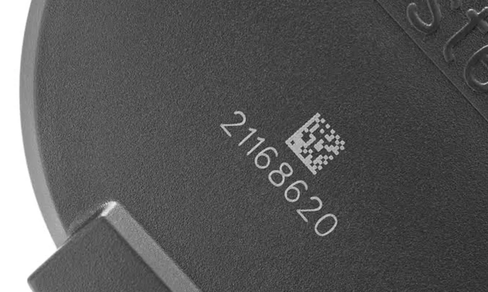
Yes—many plastics can be laser marked, but the polymer name alone is not enough to select the process. Resin grade, color masterbatch, fillers, flame retardants, recycled content, coatings and molded surface condition can all change absorption, contrast, heat response and fumes. The reliable route is to define the target mark first, then test the actual production material before the machine configuration is locked.
Request a Plastic Sample Test Ask About Material CompatibilityStep 01 · Can It Be Laser Marked?
Many Plastics Can Be Marked, but Not Every Formulation Produces a Useful Result
A plastic can be physically affected by a laser without producing an acceptable production mark. The real question is whether the final part can reach the required contrast, readability, surface quality and durability without unacceptable melting, yellowing, cracking, distortion or residue.
ABS, PP, PE, PC, PA/nylon, POM, PET, PMMA, silicone and other polymer systems can all require different wavelengths or process mechanisms. Two parts sold under the same polymer family name may respond differently when the colorant, filler, flame-retardant package, recycled content or molding condition changes.
Decision rule: treat the polymer family as the starting category, not as the final laser recipe.
Step 02 · Material Variables
Resin Grade, Masterbatch, Fillers and Surface Condition Decide the Response
For metals, alloy grade is often the key variable. For plastics, the closest equivalent is the complete compound formulation: base resin plus pigments, masterbatch, fillers, reinforcements, flame retardants, stabilizers, recycled content and any laser-sensitive additive.
Base resin and grade
Record the full commercial grade where possible. ABS, PP, PE, PC, PA, POM and PET labels are too broad to predict mark quality by themselves.
Color and masterbatch
Black, white, natural, translucent and colored parts can absorb the same laser differently. A change in masterbatch can alter contrast even when the base resin stays the same.
Fillers and reinforcement
Glass fiber, mineral fillers and other reinforcements can change heat flow, surface texture and mark appearance. Treat filled and unfilled versions as separate qualification cases.
Additive package
Flame retardants, stabilizers and laser-sensitive additives can change absorption and the mechanism that creates a dark, light or foamed mark.
Recycled content and batch variation
If recycled content or supplier batches vary in production, include that variation in the test plan instead of validating only one ideal plaque.
Surface and coating
Texture, gloss, paint, soft-touch coating, plating or other surface layers can change contrast, edge quality and heat sensitivity even when the substrate is unchanged.
| Variable | What to record | What it can change |
|---|---|---|
| Resin | Polymer family, full grade, supplier | Absorption, thermal response, baseline mark mechanism |
| Color system | Color, pigment or masterbatch reference | Contrast, absorption and visible appearance |
| Fillers | Glass fiber, mineral or other reinforcement | Texture, heat response and edge quality |
| Additives | Flame retardant, stabilizer, laser additive where known | Contrast, fumes and process window |
| Recycled content | Percentage or batch variation where applicable | Lot-to-lot consistency |
| Surface | Mold texture, gloss, coating, paint or plating | Surface damage limit, layer removal and visual finish |
Material-Specific Routes
Choose the Page That Matches the Actual Polymer Family
Use these pages when you already know the material family. Final source selection still depends on the exact production grade, color, additives and target result.
ABS Plastic Laser Marking
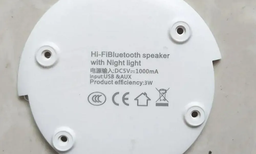
Evaluate grade, colorants, flame retardants and the required contrast or engraving effect.
Explore ABS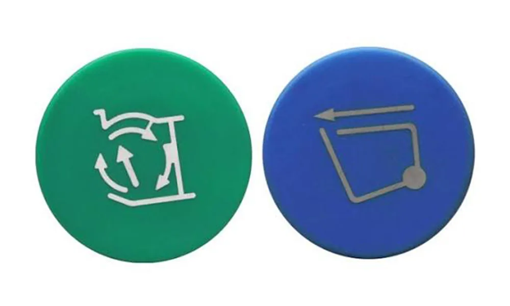
Polypropylene Laser Marking
Confirm formulation and laser-sensitive additives because unmodified PP can produce weak or inconsistent contrast.
Explore PP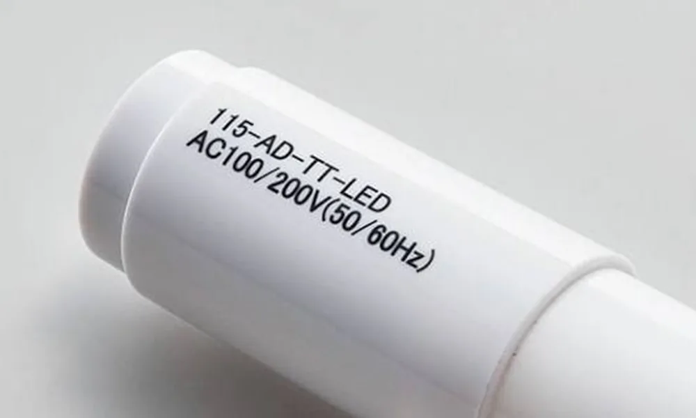
Polyethylene Laser Marking
Review density, pigment, additives and heat sensitivity before selecting a first test route.
Explore PE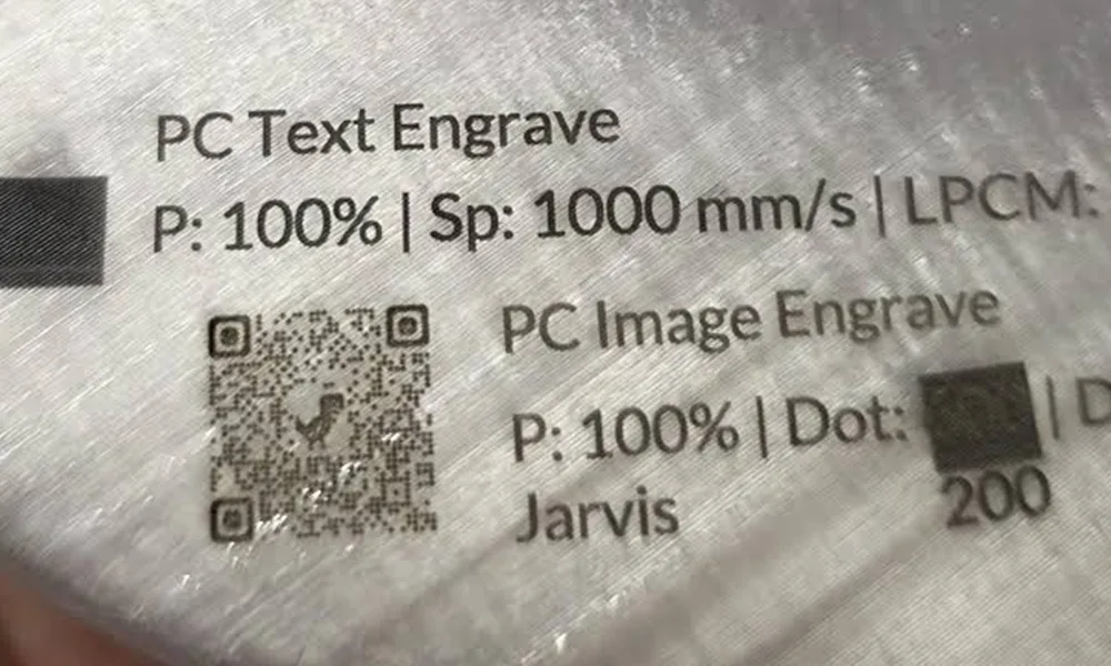
Polycarbonate Laser Marking
Balance contrast against yellowing, foaming, stress and cosmetic-surface requirements.
Explore PC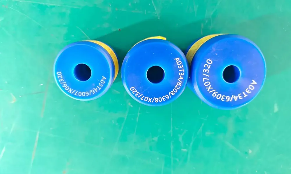
Nylon and PA Laser Marking
Account for PA grade, glass filling, moisture, color and additive package.
Explore Nylon / PA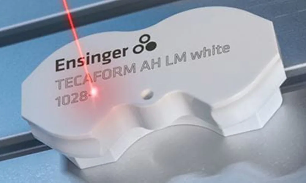
POM Acetal Laser Marking
Use the exact resin and safety documentation; formulation, fumes and contrast response require controlled qualification.
Explore POM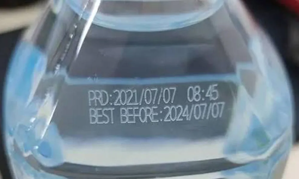
PET Laser Marking
Differentiate rigid PET, film and packaging forms, then test heat impact and code readability.
Explore PET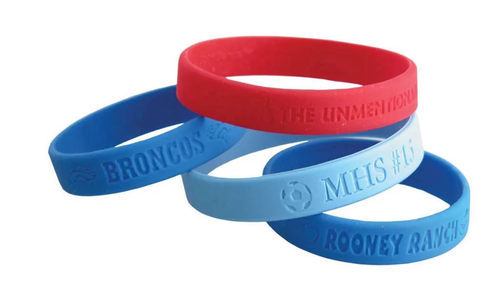
Silicone and Rubber Laser Marking
Check the exact elastomer formulation, fillers, color and safety data before testing.
Explore Silicone / Rubber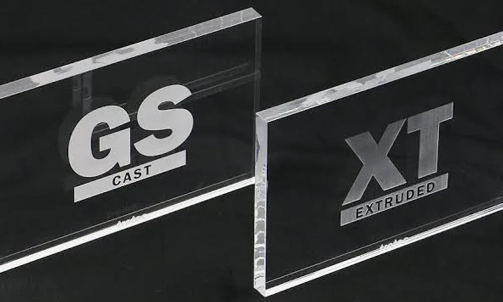
Acrylic PMMA Laser Marking
Define whether the goal is frosting, engraving, color change or another visible surface effect.
Explore Acrylic / PMMAStep 03 · Products and Why They Are Marked
Plastic Parts Are Marked for Identification, Traceability, Instructions and Branding
The same polymer may be used in very different products. Marking requirements change with the part’s function, visible surface, service environment and production method.
Electrical housings and connectors
Typical needs include part numbers, terminal identifiers, QR/Data Matrix codes, batch information and permanent legends on molded housings.
Electronics applicationsAutomotive plastic components
Connectors, trims, switches and under-hood plastic parts may need traceability, assembly identification or functional labels while preserving the surrounding surface.
Automotive & EV applicationsConsumer and appliance products
Visible housings, controls and accessories often prioritize clean logos, icons, serial numbers and consistent cosmetic appearance.
Consumer product applicationsPackaging, film and caps
Lot/date information, codes and identification marks must be evaluated together with film thickness, line speed, distortion risk and product presentation.
Tubes, cables and flexible parts
Continuous or cylindrical products add focus, motion and extraction considerations to the material-response test.
Technical molded components
Small engineering parts may need fine codes or durable identification without changing fit, sealing surfaces, clips, ribs or other functional geometry.
Step 04 · Mark Content
Define What Must Be Marked Before Choosing How to Mark It
A large logo, a small Data Matrix code and a fine molded-part identifier impose different requirements on contrast, edge definition, spot size, focus control and inspection.
Text and part numbers
Part IDs, model references, warning text or assembly information usually prioritize clear character edges and consistent appearance.
Serial, lot and date data
Variable information requires stable data transfer and repeatable placement in addition to acceptable material response.
QR and Data Matrix codes
Machine-readable codes need enough contrast and edge definition for the intended reader and verification method; visual appearance alone is not sufficient.
Logos and cosmetic graphics
Brand marks and visible graphics often make gloss, haze, edge quality and color consistency part of the acceptance criteria.
Icons, symbols and legends
Switch symbols, control legends and functional graphics can require fine detail while preserving the molded surface around the mark.
Scales or fine functional marks
Small line features need stable focus and sufficient contrast without excessive engraving depth or edge swelling.
Step 05 · Required Mark Result
Choose the Result First: Dark, Light, Foamed, Engraved, Frosted or Layer-Removed
Plastic laser marking is not one mechanism. The preferred source and parameter window depend on the result you need and the amount of surface change the part can tolerate.
Dark color change
Useful when a dark, flat mark is required. The achievable contrast depends strongly on pigment, additive package and wavelength absorption.
Light color change or foaming
A lighter or slightly raised mark can be produced on some formulations. Surface texture and height change must remain acceptable.
Engraving or ablation
Material is intentionally removed. Depth, debris, edge quality and the effect on thin walls or functional surfaces must be checked.
Frosted or matte appearance
Some transparent or glossy plastics can be marked by creating a controlled optical or surface change rather than a strong color change.
Coating removal
Painted or coated plastics require the coating and substrate to be qualified together so the top layer is removed without unacceptable substrate damage.
Machine-readable contrast
For QR or Data Matrix codes, define the reader, smallest code size and acceptance method instead of approving the mark by eye alone.
| Criterion | Question to answer |
|---|---|
| Contrast | Does the mark need to be dark, light, neutral, or simply readable by a scanner? |
| Surface integrity | Are gloss change, haze, swelling, melting, cracking or tactile depth acceptable? |
| Code readability | What reader and verification method will be used for machine-readable marks? |
| Durability | Must the mark survive abrasion, chemicals, cleaning, heat, UV exposure or another defined service condition? |
| Cosmetic consistency | How much color or appearance variation is acceptable between parts, batches or colors? |
Step 06 · Shape, Thickness and Size
Part Geometry Changes Focus, Heat Risk, Fixturing and Mark Consistency
The same resin can behave acceptably on a thick flat plaque and fail on a thin molded wall or curved surface. Geometry should therefore be included in the sample test, not treated as a machine-detail decision after the material has already been approved.
- Flat rigid parts: usually the simplest case for focus control and fixture repeatability.
- Curved or cylindrical parts: focus can change across the mark; a rotary axis, 3D focus strategy or smaller mark area may be considered depending on the geometry.
- Thin walls, films and flexible parts: lower thermal margin increases the risk of warping, shrinkage, burn-through or texture change.
- Recesses, ribs and tall features: mechanical access and focus variation can limit where the mark can be placed.
- Large parts or large mark fields: field size, feature size and positioning repeatability must be balanced rather than assuming a larger field is always better.
- Textured molded surfaces: the texture itself can reduce apparent contrast or distort fine code edges.
Step 07 · Laser Route
Choose a First Test Route From the Material Response and Required Result
Fiber, MOPA fiber, UV, green and CO2 sources can all be relevant for plastics. The first route should be chosen from absorption, heat sensitivity, desired mark mechanism, feature size and production constraints—not from a rule that one wavelength is universally best for plastic.
| Laser route | When it is reasonable to screen first | Main risks or limitations | What to verify |
|---|---|---|---|
| UV | Heat-sensitive molded parts, fine features, cosmetic surfaces, or formulations where shorter-wavelength absorption is favorable. | Not every resin absorbs usefully; cycle time and required contrast still depend on formulation. | Contrast, surface change, fine-feature quality and production speed. |
| Fiber | Engineering plastics, dark or additive-assisted compounds, and parts that respond efficiently around the fiber-laser wavelength. | Weak contrast, melting, edge swelling or heat accumulation on unsuitable formulations. | Batch/color stability, edge quality, thermal effect and readability. |
| MOPA fiber | When a wider pulse-control window may help tune contrast or heat response on a formulation already suited to the fiber route. | MOPA does not automatically make an unresponsive plastic mark well. | Whether pulse-width control materially improves the accepted process window. |
| Green | When 1064 nm response is weak and the formulation absorbs more usefully at green wavelength, including some light or semi-transparent compounds. | Material response varies widely; do not assume transparency means green is automatically suitable. | Absorption, haze, contrast, heat impact and feature quality. |
| CO2 | Surface engraving, foaming, ablation or thermal marking on polymer systems that absorb efficiently in the CO2 wavelength range. | Thermal deformation, charring, melt edge, residue or burn-through on thin material. | Surface quality, depth, distortion, residue and cycle time. |
Important: source labels are screening directions, not final recommendations. The same polymer family can move from one preferred route to another when the color, additive package, coating or target result changes.
Step 08 · Risks and Failure Modes
Most Plastic Marking Failures Come From Contrast, Heat, Surface Damage or Material Variability
A readable sample is not enough if the process damages the part, changes between batches or creates an unacceptable fume and residue burden. Review both mark quality and material safety before production approval.
Weak or unstable contrast
The chosen wavelength may not couple well with the formulation, or the pigment/additive package may vary between colors or batches.
Melting and edge swelling
Excess thermal input can soften the surface, round fine features or create raised edges around engraved areas.
Yellowing, charring or haze
Some clear, light-color or cosmetic plastics show discoloration or optical change before a strong mark is achieved.
Cracking, crazing or stress whitening
Molded stress, brittle formulations or aggressive parameters can create defects that are more serious than the mark itself.
Warping or burn-through
Thin walls, films and flexible parts have less thermal margin and must be tested in the real thickness and support condition.
Residue, smoke and odor
Decomposition products can contaminate the part, optics, enclosure or extraction path and may create safety concerns.
Fume safety is a material-acceptance decision, not an extraction shortcut
Do not treat extraction as permission to process an unidentified or unsuitable polymer. Unknown formulations, mixed recycled compounds and plastics that may contain halogens should be held until the material identity, SDS or equivalent safety information, and decomposition/emission risk have been reviewed. Extraction, filtration and enclosure are then selected for the approved process; they do not make an unknown material automatically acceptable.
Step 09 · Sample Validation
Validate a Resin / Masterbatch / Additive Matrix on Real Production Parts
The minimum useful test is not “one plastic plaque.” It is the smallest matrix that represents the combinations you will actually manufacture: resin grade, color/masterbatch, additive package, surface condition, thickness and any coating or recycled-content variation.
| Test case | Material combination | Why include it | Acceptance focus |
|---|---|---|---|
| Baseline | Production resin + current masterbatch/color + current additive package | Establishes the reference process on the exact production formulation | Contrast, mark effect, surface quality and cycle time |
| Color variants | Same resin with each production color/masterbatch that must be supported | Colorants can change absorption and visible contrast | Appearance consistency and readability |
| Filled / reinforced variants | Filled and unfilled or different glass/mineral loading where used | Fillers can change texture, heat flow and edge quality | Surface integrity and parameter window |
| Additive variants | Different flame-retardant, stabilizer or laser-additive packages where applicable | Additives can materially change both marking response and fumes | Contrast, emissions review and process stability |
| Surface variants | Gloss, texture, coating, painted or plated versions | The surface system can dominate the visible result | Layer control, gloss/haze and substrate damage |
| Geometry worst case | Thinnest wall, tight curve, recess, rib area or largest required mark field | Geometry can reduce thermal and focus margin | Warping, focus, edge quality and fit/function |
| Batch / recycled variation | Different supplier batch or recycled-content level where production uses it | Checks whether the process window remains stable outside one ideal lot | Lot-to-lot consistency |
What to record for every test
- Resin grade, supplier and batch.
- Color/masterbatch and known fillers or additives.
- Surface finish, coating and wall thickness.
- Laser route, lens/field and the qualified parameter window.
- Target mark content and smallest critical feature.
- Visual, code-readability and durability acceptance criteria.
- Fume, residue and extraction observations relevant to the approved material.
When to stop and re-test
- Resin supplier or commercial grade changes.
- Masterbatch, pigment or part color changes.
- Filler, flame-retardant or other additive package changes.
- Recycled-content level or material source changes.
- Mold texture, coating, paint or surface finish changes.
- Wall thickness, geometry or mark location changes enough to affect focus or heat flow.
- The required code size, contrast, durability or cycle-time target changes.
Evidence rule: do not label a resin/masterbatch/additive combination as “tested” unless there is an actual sample record or project test record for that combination. Until then, this matrix is a qualification plan, not proof of a completed test.
Step 10 · Machine Configuration and Quotation
Lock the Machine Configuration Only After the Material and Mark Result Are Proven
Once the sample test identifies a stable process window, the equipment can be configured around the real part, mark field, positioning method, throughput and safety requirements. This is where a material test becomes a machine specification rather than a generic laser recommendation.
- Laser source: wavelength/source family and the pulse behavior required by the validated process.
- Optics and field: lens/marking field chosen around feature size, part size and working distance.
- Focus strategy: fixed focus, Z adjustment or a 3D/focus-control option where geometry requires it.
- Part handling: fixture, rotary, custom nest or other positioning method for repeatability.
- Vision: considered when part orientation or mark position varies; vision does not by itself solve height/focus variation.
- Extraction and enclosure: selected from the approved material/process and the required operator/environmental controls.
- Data and line interface: variable codes, triggers, encoder or production-line integration when the application needs them.
- Acceptance baseline: keep the approved sample and criteria as the reference for machine setup and production handover.
Send these inputs with your RFQ

Frequently Asked Questions
Plastic Laser Marking FAQs
Can all plastics be laser marked?
No. Many plastics can be marked, but some formulations produce weak contrast, excessive heat damage or unacceptable fumes. The exact production formulation and target result should be tested before equipment is selected.
Why can two parts made from the same plastic mark differently?
The polymer family name does not capture colorants, masterbatch, fillers, flame retardants, recycled content, laser additives, coatings or molding condition. These variables can change absorption, contrast and heat response.
Do plastics need laser marking additives?
Some formulations mark well without an additive; others need a laser-sensitive additive to reach the required contrast or process speed. The final compound should be validated before the machine route is locked.
Is UV laser always the best choice for plastic?
No. UV is often screened for heat-sensitive or fine-feature applications, but fiber, MOPA fiber, green or CO2 can be better for other formulations and mark mechanisms. Source selection should follow sample results.
Can PVC or an unknown halogenated plastic be tested if extraction is installed?
Extraction is not a substitute for material acceptance. Unknown or potentially halogenated formulations should be held until material identity, safety data and decomposition/emission risks have been reviewed.
What should I send for a plastic sample test?
Send final molded or coated parts if possible, plus resin grade, supplier, color/masterbatch, known fillers/additives, mark artwork or code, required mark effect, cycle-time target, durability criteria and safety data.
From Material Test to Machine Selection
Send the Actual Plastic Part and the Result You Need
Zhuorui can use the production material, mark content, geometry, acceptance criteria and throughput target to narrow the test route and configuration. The quotation should follow the validated material response rather than a generic “plastic laser” assumption.