
Laser Marking Machine Applications – Plastic Tube
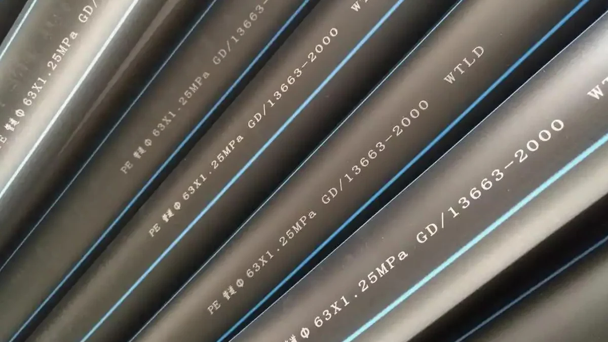
Plastic Tube Laser Marking
Plastic tube laser marking depends on the actual polymer formulation, wall thickness, diameter, surface condition, mark content and production motion. A useful setup must produce the required contrast and code quality at the real production rate without unacceptable melting, charring, burn-through, distortion or position drift.
- Tube material, color, wall thickness and surface condition
- Mark content, size, readability and durability target
- Line speed, mark position and repeat interval treated as separate inputs
- Sample and line tests mapped to the final machine configuration
Plastic Tube / Workpiece Scope
Which Plastic Tubes Use Laser Marking?
Define two dimensions separately before choosing the marking setup: the physical tube form and the production or handling state. A tube can be flexible and reel-fed at the same time, or rigid and supplied as cut lengths, so these are not four mutually exclusive product categories.
Tube Form
Flexible plastic tubing
Soft tubing can wander, sag or rotate as it moves. Guiding, support and tension may matter as much as the laser source when mark position must stay stable.
Rigid or semi-rigid tubing
Rigid small-diameter tubes are easier to support, but curvature, diameter range and the usable focused marking width still determine code size and placement.
Production / Handling State
Continuous or reel-fed tubing
Extrusion and reel-to-reel production add line speed, product slip, acceleration, stop-start behavior and repeat-spacing control to the marking task.
Cut-length tubes
Individual tube sections shift the problem toward fixture datum, orientation, loading cycle, changeover and pieces-per-minute throughput rather than continuous line synchronization.
If the workpiece is a cable jacket or a heat-shrink sleeve, use the related application pages at the end of this guide. This page focuses on plastic tubing itself.
Why Mark and What to Mark
Why Are Plastic Tubes Marked?
The marking requirement should be defined before the laser is selected. The reason for the mark determines the required content, size, durability, position tolerance and verification method.
Product identification
Part numbers, model codes, size, specification or brand information help distinguish one tube from another during assembly, storage, installation or service.
Batch and production traceability
Lot, date, shift, reel, serial or recipe data can connect the finished tube to the production record required by the manufacturer or customer.
Length and position reference
Meter or foot marks, cut references and repeated identifiers can support measuring, cutting, installation and process control on continuous tubing.
Customer or project requirements
Specified wording, symbols, code formats, placement and durability conditions should be treated as project inputs and confirmed during sample acceptance.
Marking Content
What Is Usually Marked on Plastic Tubes?
A short identifier at a fixed location is a different production task from dense variable data, meter marks or compact 2D codes. Content burden directly affects marking time, feature size and the available process window.
| Marking task | Typical content | What changes the process | Validation focus |
|---|---|---|---|
| Product identification | Model, part number, size, grade reference, rating or brand. | Character height, tube diameter, surface color, mark orientation and available marking width. | Legibility and stable placement after normal handling. |
| Length or repeat marks | Meter count, foot count, cut reference or repeated identifier. | Line-speed reference, repeat pitch, product slip, acceleration and stop-start behavior. | Measured interval accuracy across the intended speed range. |
| Batch or serial data | Lot, date, shift, reel, serial number or production recipe. | Data source, message changeover, trigger logic, restart behavior and product-to-data binding. | Correct data at start, stop, pause, restart and batch change. |
| Compact machine-readable codes | Barcode, QR or Data Matrix where the tube diameter and mark area allow. | Module size, quiet zone, curvature, focus range, contrast and reader angle. | Reader verification under the actual lighting, distance and orientation used in production. |
| Customer-specified marking | Required wording, symbol, spacing, traceability or location pattern. | Project specification, mark position tolerance, durability requirement and approval method. | Documented sample approval against the customer-defined requirement. |
Result Variables
What Determines the Plastic Tube Laser Marking Result?
The material name alone is not enough. A workable process window is created by the interaction between formulation, wall construction, surface condition, geometry, mark content and production motion.
Polymer formulation
Resin family, grade, pigment, filler and laser-responsive additives can change absorption, color response and thermal behavior. Two tubes sold under the same generic polymer name can mark differently.
Wall thickness and construction
Thin walls reduce the margin for excessive local heating. Multi-layer, coated or printed constructions also change which layer the laser interacts with first.
Surface color and condition
Color, gloss, texture, contamination, release agents, oil or a surface layer can change contrast and consistency across batches or suppliers.
Diameter and curvature
Smaller diameters increase curvature across the mark. A code that spans too far around the tube can move outside the best focus region or become difficult to inspect.
Mark size and content density
Small characters, dense codes, multiple text lines and long messages require more usable resolution and marking time than a short identifier.
Production motion and variation
Line speed, tube wander, rotation, acceleration, slip, SKU changes and supplier or color variation can turn a good bench sample into an unstable production process.
Target Result
What Result Should You Target?
Define the acceptable result before comparing sources or power levels. The target should describe both mark quality and what the tube must still survive after marking.
- Readable contrast: the text or code is readable under the actual visual or scanner condition used by the customer.
- Surface integrity: no unacceptable melting, charring, burn-through, deformation, rough residue or layer exposure.
- Feature quality: character edges, smallest features and code modules remain distinguishable at the required size.
- Position repeatability: the mark stays within the required longitudinal and circumferential location tolerance.
- Repeat-spacing accuracy: repeated marks or length references remain within the required interval tolerance.
- Durability: readability and surface condition remain acceptable after the bending, rubbing, cleaning, heat or installation tests that actually apply to the project.
Geometry, Positioning and Tube Handling
How Do Tube Geometry and Handling Affect the Setup?
A tube is not a flat plate. Diameter, curvature, flexibility and motion determine how much of the surface stays in the usable focus range and how repeatably the target area can be presented to the laser.
| Tube condition | Typical risk | What to evaluate |
|---|---|---|
| Small diameter / strong curvature | Part of a wide mark moves away from the best focus plane or becomes difficult to scan visually. | Tube OD, usable mark width, character height, optical field, focus tolerance and reader angle. |
| Flexible moving tube | Lateral wander, sag or twist shifts the mark location and focus. | Guides, support, tension, mark-zone stability and whether the surface orientation is controlled. |
| Continuous extrusion or reel feed | Motion, slip and speed changes affect mark timing and repeat spacing. | Line-speed range, encoder reference, trigger location, product slip, acceleration and stop-start behavior. |
| Cut-length tube | Manual or automatic loading changes datum and orientation from part to part. | Fixture datum, orientation feature, loading method, cycle time and changeover between diameters. |
| Specified circumferential position | The mark rotates away from the required viewing or assembly position. | Orientation control, mechanical reference and whether indexed rotation is actually required. |
Motion Inputs
Keep Line Speed, Mark Position and Repeat Interval Separate
These three values answer different engineering questions. Combining them into one vague moving-line value makes it impossible to diagnose whether the problem is available marking time, placement accuracy or repeat-spacing accuracy.
| Input | How to record it | What it controls | Typical failure if it is unstable |
|---|---|---|---|
| Line speed | Minimum, nominal and maximum production speed with a stated unit such as m/min; include acceleration and stop-start behavior. | Available marking time and whether the required content fits inside the moving mark window. | Weak or incomplete characters, shortened content window or unstable result during speed changes. |
| Mark position | Distance from a defined product or machine datum, plus orientation around the tube when relevant. | Where the code appears on each tube or repeat segment. | The code drifts longitudinally or rotates away from the required location. |
| Repeat interval / pitch | Required spacing in mm, m or another specified unit, with the allowed tolerance. | Distance between repeated identifiers, length marks or cut references. | Spacing accumulates error because of slip, scaling, trigger or motion-reference problems. |
| Available mark window | Usable length on the moving tube and whether the content is longitudinal, transverse or orientation-sensitive. | Maximum content length, number of lines and code density that can be completed in the available time. | The message no longer fits even though the line speed itself has not changed. |
Laser Source Screening
Which Laser Route Should Be Tested First?
Start from the actual tube formulation and target result, then compare a small number of credible source routes. Do not choose a laser from tube color or wattage alone, and do not treat a flying system as a fourth laser wavelength.
| Starting route | When it may be screened | What the test must establish |
|---|---|---|
| UV | Selected polymer formulations where fine features or a smaller thermally affected mark are important. | Contrast, smallest readable feature, surface damage, focus tolerance and the achievable rate on the actual tube. |
| CO2 | Selected polymers or surface layers that respond effectively to the available CO2 output and can accept the resulting surface interaction. | Contrast, melting or charring, residue, fume-extraction demand, character quality and marking rate. |
| 1064 nm Fiber / MOPA Fiber | Selected formulations designed or found by testing to respond at the fiber wavelength. MOPA is a fiber-laser route with additional pulse-control flexibility, not a separate material family. | Color response, thermal effect, repeatability, pulse-window sensitivity and whether the required content can be completed at the target rate. |
Important: a flying or online marking system is a motion-and-integration architecture, not a laser source. First establish which source can make an acceptable mark; then verify whether that source can maintain the result under the required production motion.
Failure Diagnosis
What Usually Fails, and What Should You Check First?
A failed mark is more useful when the symptom points to the next test. Separate material-response problems from focus, motion, positioning and data-control problems before changing power or replacing equipment.
| Observed failure | Likely variables to separate | Next check |
|---|---|---|
| Contrast is too low | Formulation, pigment/additive response, wavelength route, focus and delivered energy. | Compare controlled source/parameter samples on the same tube lot before changing the production hardware. |
| Melting, charring or burn-through | Wall thickness, local energy, focus, scan speed, pulse strategy and heat accumulation. | Inspect the marked cross-section or surface condition and reduce process severity while preserving readability. |
| Excessive residue or fumes | Material formulation, surface layer, process severity and extraction condition. | Separate the mark-quality requirement from the extraction requirement; verify both on the intended process window. |
| One side of the mark is weak or blurred | Tube curvature, runout, focus range, tube support and mark width. | Reduce the mark span or stabilize the tube and compare focus across the full marked area. |
| Characters stretch, compress or become incomplete at speed | Line-speed measurement, moving-mark compensation, available mark window and message length. | Record actual line speed and compare mark quality at minimum, nominal and maximum conditions. |
| Repeat spacing drifts | Encoder scaling, product slip, trigger timing and motion reference. | Measure repeat pitch over a long enough run to separate constant offset from accumulating error. |
| Mark position wanders | Tube guiding, lateral movement, rotation, trigger location and datum definition. | Measure the physical tube path first; do not treat a mechanical presentation problem as a laser-power problem. |
| Data is missing, duplicated or wrong after restart | Trigger sequence, data queue, PLC/controller state, recipe and restart logic. | Test start, stop, pause, restart and batch change as separate production events. |
Production Workflow
How Does Plastic Tube Laser Marking Fit into Production?
Production readiness means more than making a good sample. The tube must be presented consistently, the correct data must be loaded, motion must be referenced correctly, the mark must be verified and abnormal events must have a defined response.
- 1. Present and guide the tube: stabilize the mark zone, diameter, orientation and focus condition.
- 2. Load the correct recipe and data: bind the intended SKU, message and variable-data source to the product being marked.
- 3. Reference motion: use the required trigger, encoder or station signal when the tube is moving.
- 4. Mark inside the available window: complete the message without exceeding the real line-speed or cycle-time limit.
- 5. Verify the result: check content, readability, mark position and repeat spacing at the defined frequency.
- 6. Handle failures: define alarm, reject, stop or operator response when the mark or data is not acceptable.
- 7. Test restart and changeover: verify pause/restart, reel change, batch change and diameter/SKU change conditions.
- 8. Record what matters: retain the production or quality data required by the project rather than relying on one good setup sample.
Production Mode
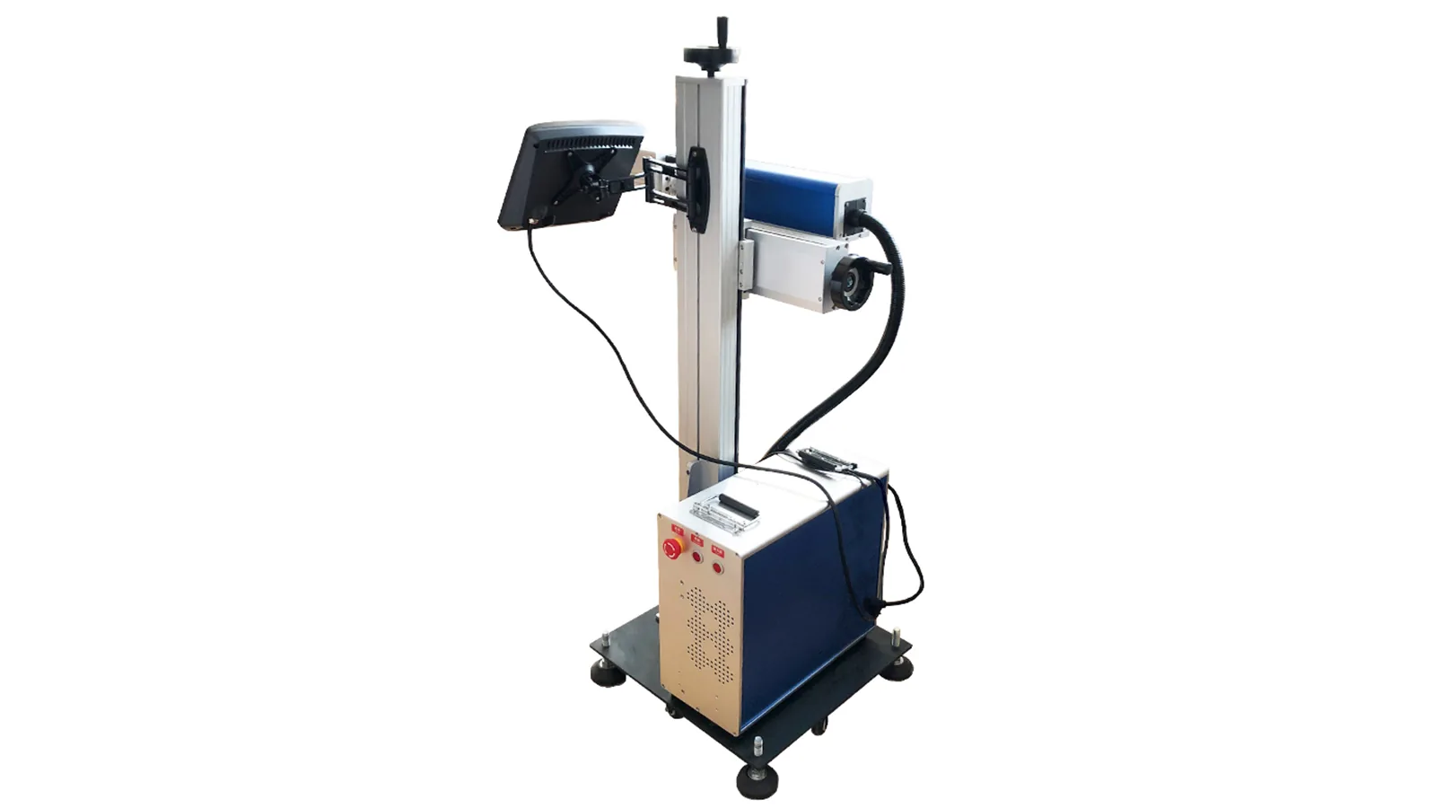
Static, Moving-Line and Flying Setups Solve Different Problems
| Production mode | Primary input | What usually decides the architecture |
|---|---|---|
| Offline / cut-length station | Parts per minute, loading method, fixture datum and changeover time. | Fixture design, manual or automatic loading, cycle time, field size and operator workflow. |
| Continuous moving tube | Minimum, nominal and maximum line speed; mark window; repeat interval; tube stability. | Flying marking capability, encoder/trigger reference, guide position and whether the required content fits at maximum speed. |
| Reel-to-reel | Feed speed, tension, unwind/rewind behavior, slip and reel change. | Motion reference, tension control, guide strategy, stop/restart behavior and repeat-spacing verification. |
| Integrated production line | Line signals, data source, verification requirement, alarm/reject behavior and available installation space. | Controller, PLC/MES communication, sensor placement, reader/vision, extraction and enclosure integration. |
For moving production, review the Flying & Online Laser Marking Solution after the laser source and acceptance target have been established.
Sample and Running-Line Acceptance
How Should Plastic Tube Laser Marking Be Validated?
Use two gates. First prove that the actual tube can produce the required mark without unacceptable damage. Then prove that the same result remains stable under the real production motion, data and throughput conditions.
Gate 1 – Sample Feasibility
Test the actual tube formulation, color, wall thickness, diameter and required mark. Compare credible laser routes and confirm contrast, smallest feature, surface integrity and any project-specific bend, rub, cleaning, heat or installation requirement.
Pass only when: the accepted result can be reproduced on representative tube samples within a documented process window.
Gate 2 – Running-Line Acceptance
Test minimum, nominal and maximum line speed; mark position; repeat interval; stop/restart; data change; tube wander; batch or reel change; and the actual verification method.
Pass only when: mark quality, data correctness, placement and repeatability remain acceptable across the intended production conditions.
Test Brief
What to Provide Before Testing
| Input | What to provide | Why it matters |
|---|---|---|
| Tube sample | Actual tube, polymer/grade information where available, supplier, color, wall thickness, layer or coating condition and diameter range. | Defines the material and geometry that must be tested rather than assumed. |
| Mark content | Text, logo, code type, character height, code size, repeat interval and variable-data format. | Controls resolution demand, available marking time and verification method. |
| Line speed | Minimum, nominal and maximum speed with units, plus acceleration and stop-start behavior. | Defines the available moving mark window and the hardest production condition. |
| Mark position | Required position from a defined datum and any circumferential orientation tolerance. | Defines the guiding, trigger, fixture or orientation-control requirement. |
| Repeat interval | Required pitch or meter-mark spacing with tolerance. | Defines how repeat spacing must be referenced and verified. |
| Acceptance criteria | Contrast/readability method, code-reader requirement, permitted surface change, durability tests and any fume/extraction constraints. | Prevents a visually attractive sample from being mistaken for a production-approved result. |
| Production volume | Line output or parts per minute, batch size, shift pattern, operating hours and expected duty cycle. | Separates a short sample test from the thermal, handling, automation and service demands of real production. |
| Integration context | Static station, moving line, reel-to-reel, available encoder/trigger, PLC/MES or reader requirement, installation space, voltage and extraction condition. | Determines the mechanical, control and support architecture around the validated laser process. |
Test Result to Machine Configuration
How Do Test Results Determine the Final Machine Configuration?
The final configuration should be a response to observed test results and production constraints, not a wattage guess. Each failed or limiting condition should point to the source, optics, focus, mechanics, motion reference, control, verification or extraction feature that actually addresses it.
| Test observation or production requirement | What it changes in the final configuration |
|---|---|
| Only one source route produces the required contrast and surface condition. | Select that validated laser-source family and keep its tested process window as the basis for the production configuration. |
| Small characters or compact codes lose definition. | Review field size, lens choice, focus condition, code dimensions and whether the required feature size is realistic on the tube curvature. |
| Diameter or height variation moves the surface outside the acceptable focus range. | Add the required Z adjustment, height-control method or another validated focus strategy instead of assuming one fixed setup covers all diameters. |
| The tube wanders, twists or sags through the mark zone. | Add or redesign guides, supports, tension control or orientation features before increasing laser power. |
| Mark position changes with line motion. | Review trigger location, motion reference, encoder use and synchronization method. |
| Repeat interval accumulates error. | Review encoder scaling, product slip, measuring reference and the method used to verify pitch over a production run. |
| The process is acceptable when static but not at production line speed. | Review source capability, optics, message burden, moving-mark strategy and the flying architecture needed to complete the mark inside the available window. |
| Variable data comes from PLC, MES or another production system. | Specify controller communication, data handshake, recipe management and restart behavior as part of the machine package. |
| Automatic code verification or fail handling is required. | Add the appropriate reader or vision method plus alarm, reject or stop logic; define what constitutes a failed read or wrong code. |
| The validated process creates meaningful residue or fume load. | Size extraction, enclosure and maintenance access for the validated process rather than treating ventilation as an afterthought. |
| High output, long shifts or frequent SKU changes are required. | Use production volume, cycle time, duty cycle and changeover frequency to define automation level, cooling/service margin, fixture or guide changeover and operator workflow. |
Recommended decision record: keep the accepted sample, test settings, tube identification, line-speed range, mark position, repeat interval, verification result and the configuration decisions that followed from the test. That makes later supplier, color, diameter or SKU changes easier to revalidate.
Send the actual tube samples, mark file, production data and acceptance criteria to Contact Us. Use Request a Quote for standard equipment review and OEM & Custom Inquiry when the project requires line integration, PLC/data exchange, custom guiding, automatic verification or other non-standard engineering.
Next Step
Start with the Actual Tube, Required Mark and Production Condition
A useful review starts with the tube formulation and wall, the result you need, how the workpiece is positioned, and how fast production must run. From there, sample testing can screen the laser route and running-line validation can define the final optics, motion, control, verification and extraction configuration.
Prepare for faster review: actual tube samples; polymer/grade information where available; wall thickness; diameter range; color or coating; marking content and size; line speed or cycle time; mark position; repeat interval; production volume; shift pattern and duty cycle; encoder/trigger availability; target contrast and readability; permitted surface change; durability tests; extraction constraints; integration signals; voltage and destination.