Fiber laser technology guide
Fiber Laser Marking Technology
Fiber laser marking uses a near-infrared laser generated and amplified in an optical-fiber gain medium, then directs and focuses that beam onto a workpiece to create a controlled material response. In industrial marking, the technology is especially well suited to metals because it combines a compact fiber source, fast galvo scanning, a small focused spot, and a process window that can produce permanent contrast, annealed marks, coating removal, or material removal depending on the application.
A material is not qualified for fiber marking by a simple yes-or-no check. A workable process depends on the exact material, surface condition, required mark, optical setup, and pulse-and-scan conditions, and it must repeat without unacceptable heat, damage, distortion, or cycle time.
Fiber Laser Technology in 30 Seconds
| Question | Practical answer |
|---|---|
| What is a fiber laser? | A laser that generates and amplifies light in a doped optical-fiber gain medium. |
| What wavelength is commonly used for marking? | Near-infrared output, commonly around 1.06 μm. The exact nominal wavelength depends on the source. |
| Where is it strongest? | Industrial metal marking and selected coated, plated, and polymer applications. |
| What can it produce? | Surface contrast, annealing, engraving, ablation, coating removal, serial numbers, logos, QR codes, and Data Matrix marks. |
| What actually controls the result? | Material and surface condition together with pulse behavior, average power, frequency, scan speed, hatch spacing, focus, lens choice, and number of passes. |
| Is more wattage always better? | No. Wattage changes available process capacity, but it does not define marking quality by itself. |
| When should another laser be compared? | Compare UV for heat-sensitive or formulation-dependent plastics, CO₂ for many organic materials, and UV or green sources when transparent or wavelength-sensitive materials narrow the fiber process window. |
What Is Fiber Laser Marking Technology?
“Fiber laser” describes the laser-source architecture. “Laser marking” describes the manufacturing process performed on the workpiece. A fiber laser can therefore be used for marking, engraving, ablation, and other surface-processing tasks, while other laser-source families can perform some of the same process categories through different wavelength and pulse characteristics.
What makes a laser a fiber laser?
In a fiber laser, the gain medium is optical fiber that has been doped with a rare-earth element. Ytterbium-doped fiber is widely used in industrial near-infrared marking sources. Pump diodes inject optical energy into the doped fiber, where the light is amplified before the output is delivered to the marking head.
The source architecture sets the wavelength range and pulse behavior available to the process. Those source characteristics then interact with scanning speed, focus, field size, and the material itself.
Fiber laser marking versus laser marking in general
Laser marking is a broader process category. Fiber is one source family within that category. UV, CO₂, and green laser systems use different source architectures and wavelengths, which changes how strongly a given material interacts with the beam and how wide the usable process window may be.
“Laser marking” and “fiber laser marking” are not interchangeable terms. A material can be laser-markable without being a good match for a near-infrared fiber source.
MOPA within the fiber-laser family: MOPA is a pulsed fiber-laser architecture with broader pulse-control capability. It remains a fiber laser; the practical distinction is the available pulse-control range, which can affect the process window for specific marking applications.
How Does a Fiber Laser Marking System Work?
The process can be understood as a chain: pump energy enters the doped fiber, the laser beam is generated and amplified, the marking head steers the beam, the focusing lens concentrates it on the workpiece, and the material converts part of that optical energy into a thermal or physical response.
Generating and amplifying the laser beam
Pump diodes supply energy to the doped fiber. Inside the fiber, stimulated emission amplifies the light until the source produces a controlled laser output. Industrial marking sources are commonly operated in a pulsed regime because pulse timing and energy delivery give the process additional control over contrast, heating, and material removal.
The source does not determine the final mark by itself. It defines the energy and pulse behavior that are available; the optical system and scan strategy determine how that energy is placed on the surface.
Steering the beam across the workpiece
Most industrial fiber markers use galvanometer-driven mirrors to steer the beam rapidly in two axes. The part can remain stationary while the beam draws text, logos, codes, or filled areas inside the available field.
This architecture supports high-speed identification work, but scan-head capability should not be confused with finished cycle time. A shallow serial number and a deep engraved logo can use the same galvo system yet require very different exposure, hatch density, pass count, and process time.
Focusing the beam
The steered beam passes through a focusing lens, commonly an F-theta lens, before reaching the workpiece. Lens choice affects the usable marking field, working distance, spot behavior, and achievable energy density at the surface.
A larger field may be useful for bigger parts or multi-part fixtures, but the optical system involves trade-offs. Field size, spot size, resolution, and process intensity cannot be treated as independent specifications. A configuration selected only for the largest field can reduce the process margin available for fine details or demanding material removal.
Turning laser energy into a mark
When the focused beam reaches the surface, the material absorbs part of the incident energy. Depending on the material and the way energy is delivered, the result can range from a visual surface change with minimal removal to melting, vaporization, or removal of a coating or substrate.
The mark is therefore a controlled material response. “Fiber marking” is not one single mechanism. Annealing, surface contrast, coating ablation, and engraving all require different energy-delivery conditions even when the same laser family is used.
Why Is Fiber Laser Technology So Effective for Metal Marking?
Fiber laser systems are widely used for industrial metals because near-infrared fiber sources can be focused into a small spot, scanned rapidly, and operated over process conditions that are useful for many metallic surfaces. Their usefulness comes from the combination of wavelength, beam delivery, focused energy density, and controllable exposure rather than from any one specification alone.
Near-infrared output is a strong industrial starting point for many metals
Many common engineering metals can be processed effectively with near-infrared fiber-laser energy. Stainless steel, carbon and alloy steels, aluminum, titanium, nickel alloys, and many coated or plated surfaces are frequent candidates.
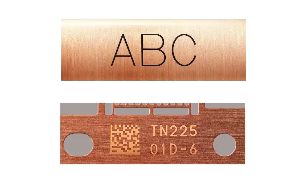
That does not mean all metals behave the same way. Reflectivity, thermal conductivity, alloy composition, surface finish, oxide condition, coating thickness, and required mark all change the result. Copper and brass, for example, can require a narrower or more carefully developed process window than many steels.
Copper is a useful example of why “fiber can mark metal” is too broad a rule. Its high reflectivity and high thermal conductivity make useful energy coupling more demanding than on many steels. In practice, focused intensity and pulse conditions can matter more than average wattage alone, so copper applications should be validated on the actual alloy, finish, and required mark.
A small focused spot creates useful local energy density
Concentrating the beam into a small spot makes it possible to create fine text and compact codes, but the same optical concentration can also support material removal when the application requires engraving or ablation.
A smaller spot and higher local intensity are not automatically better. A production process may need more field area, more focus tolerance, or more stable coverage rather than the smallest theoretical feature size. Optical selection should follow the actual acceptance criteria.
Galvo scanning supports fast digital marking
Because the beam can be redirected electronically at high speed, fiber systems are well suited to variable data such as serial numbers, date codes, logos, QR codes, and Data Matrix symbols. There is no physical tool to change when the digital content changes.
However, the useful throughput of the complete process still includes exposure time, loading, positioning, focusing, extraction, inspection, and any repeated passes. Fast beam steering cannot compensate for a process window that requires excessive heat input or many passes to achieve the target result.
What Materials Can a Fiber Laser Mark?
Material fit should be judged by the required result on the real surface, not by a generic material name. The same substrate can be a strong candidate for one marking mechanism and a poor candidate for another.
| Material or surface | Typical fiber-laser fit | Common results | Main qualification |
|---|---|---|---|
| Stainless steel | Strong | Contrast, annealing, engraving, traceability marks | Grade, finish, required appearance, and corrosion-related requirements can change the acceptable process window. |
| Carbon and alloy steel | Strong | Identification, contrast, engraving | Surface treatment, oxide condition, and required depth matter. |
| Aluminum | Strong | Contrast, engraving, codes | Alloy and surface finish can materially change contrast and removal behavior. |
| Anodized aluminum | Strong for many marking tasks | High-contrast marking, selective layer removal | Anodized-layer type, color, and thickness affect the result. |
| Titanium | Strong | Contrast, annealed appearance, engraving | Thermal response and cosmetic requirements need control. |
| Nickel-based alloys | Generally strong | Identification and engraving | Confirm the exact alloy and acceptance criteria. |
| Copper | Application dependent | Contrast or engraving | Reflectivity and thermal conductivity can reduce process margin; validate the real material and result. |
| Coated or plated metals | Application dependent | Coating removal, contrast, exposed substrate | The coating and substrate must be evaluated as one system. |
| Selected engineering plastics | Application dependent | Color change, contrast, limited surface modification | Polymer chemistry, pigment, fillers, and laser-sensitive additives dominate the response. |
Strong candidates are still application-specific
Steel, stainless steel, aluminum, titanium, and many coated metals are common fiber-laser candidates, but material compatibility is only the first filter. A process intended to create an annealed appearance is not the same process as one intended to remove material. The required result determines which part of the fiber-laser process window matters.
Conditional materials need real-surface validation
Copper, brass, plated surfaces, and selected plastics deserve more caution because small changes in surface condition or formulation can shift the response significantly. For plastics in particular, a polymer family name is often not enough. Pigment, filler, colorant, and laser-sensitive additives can decide whether the material develops usable contrast, melts, foams, or shows little response.
What Types of Marks Can a Fiber Laser Produce?
A fiber laser can produce several different result classes, and each depends on a different material response. Process settings should be chosen for the required function of the mark rather than from a single generic “fiber parameter” recipe.
Surface contrast marking
For identification work, the goal is often to create a visible optical change without intentionally removing much material. The acceptance criterion may be human readability, machine readability, or a defined contrast level. Those are different requirements and should not be treated as equivalent.
Annealing
On suitable metals such as stainless steel or titanium, controlled thermal exposure can create a visible oxide-related change while minimizing intentional material removal. The useful window is bounded by heat: too little exposure may produce weak contrast, while excessive exposure can create unwanted surface change, damage, or a result that no longer behaves like an annealed mark.
Not every dark metal mark is an annealed mark. Annealing depends on a material that can develop a visible oxide-related color response under controlled heating; steels and titanium are common candidates, while aluminum and many non-ferrous metals require a different marking mechanism. The mechanism should be identified from the material response, not from appearance alone.
Engraving and material removal
When the process must create measurable depth, energy delivery is shifted toward material removal. Repeated passes can increase depth, but they also increase cycle time and cumulative heat. This creates a practical trade-off between removal rate, edge quality, surface texture, thermal load, and throughput.
For that reason, “add more passes” is not a complete engraving strategy. Scan speed, pulse behavior, hatch, focus, and the removal efficiency of each pass all matter.
Ablation and coating removal
Fiber lasers can be used to remove paint, anodized layers, coatings, or other surface treatments when the coating responds differently from the substrate. Selectivity is the key requirement: enough energy must reach the layer being removed while substrate damage remains within the acceptance limit.
A clean-looking result is not sufficient if the substrate has been overheated, roughened, or thinned beyond what the application allows.
Black and high-contrast marking
High-contrast and black marks are possible on selected materials, but they are not universal outcomes of every fiber laser. The achievable appearance depends on material, surface finish, source pulse behavior, focus, scan strategy, and the width of the stable process window.
Traceability codes and variable data
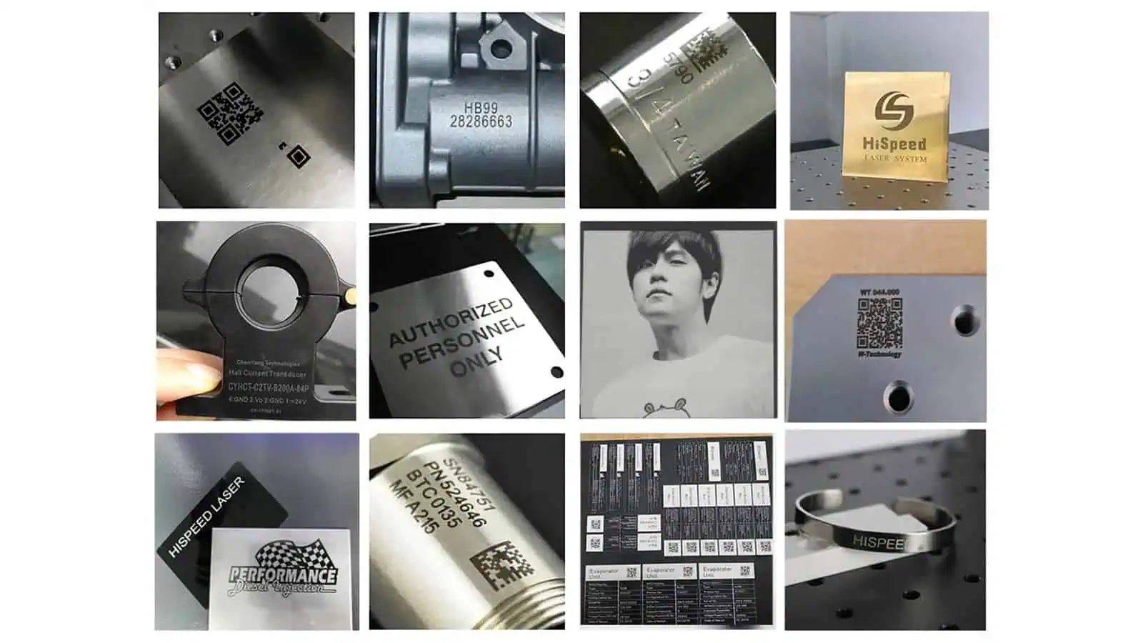
Serial numbers, text, logos, QR codes, and Data Matrix symbols are common fiber-laser applications because galvo systems can change digital content without changing physical tooling. For machine-readable codes, visual appearance alone is not enough: cell definition, contrast, distortion, surface reflection, and any required grading method must be considered in validation.
If the drawing, customer specification, or traceability system requires formal verification of a direct-part-marked 2D code, acceptance should be tied to the specified grading method rather than to a handheld-reader “pass.” ISO/IEC 29158, commonly referred to as AIM DPM, is the industry framework used for direct part mark quality evaluation.
Which Parameters Actually Control a Fiber Laser Mark?
Fiber marking is a coupled process. The most important mistake to avoid is treating each parameter as if it had one isolated effect. The visible result comes from how the source, optics, motion, and material interact over time and area.
For a regular pulse train, average power ≈ pulse energy × repetition frequency. This does not mean every commercial source keeps pulse energy constant across its full frequency range; source architecture and operating limits still matter. The relationship also shows why average power, pulse energy, and repetition frequency should not be treated as three independent knobs that can all be maximized at the same time. For a deeper treatment of the interaction, see the Pulse Width and Frequency Guide.
| Variable | What it changes directly | Why it matters in practice |
|---|---|---|
| Average power | Energy available per unit time | Changes process capacity and possible throughput, but does not define quality alone. |
| Pulse energy | Energy delivered in each pulse | Changes local material response and removal intensity. |
| Repetition frequency | Pulse timing and spacing for a given scan condition | Changes overlap, energy distribution, and heat accumulation. The exact relationship depends on source architecture. |
| Pulse width | Duration of energy delivery when the source allows it to be controlled | Changes peak-power and thermal behavior; available control range depends on the fiber source. |
| Scan speed | How quickly the beam moves over the surface | Changes exposure per unit length, pulse spacing, heat input, depth, and cycle time. |
| Hatch spacing | Distance between adjacent fill lines | Changes line overlap, fill uniformity, cumulative heat, and processing time. |
| Focus position | Spot size and energy density at the workpiece | Changes process intensity, sharpness, and tolerance to part-height variation. |
| Lens and field size | Optical field, working distance, and spot behavior | Creates a trade-off between marking area, resolution, and process intensity. |
| Number of passes | Repeated exposure of the same geometry | Can increase depth or cumulative effect, but also increases heat and cycle time. |
Power is a capacity variable, not a quality score
A higher-wattage source gives the process more available energy per unit time, which can be valuable for removal rate or throughput. It does not guarantee a cleaner, darker, sharper, or more stable mark. If the energy is delivered with the wrong overlap, focus, or thermal balance, additional power can simply push the process outside the acceptable window faster.
A 50 W source is not automatically better than a 30 W source simply because its nominal power is higher. The correct source is the one that provides enough process margin for the required result and cycle time.
Frequency and scan speed jointly control pulse spacing
Repetition frequency describes how often pulses are emitted, while scan speed describes how far the beam moves over time. Those two variables together determine how closely successive pulses are placed along the scan path. As a first-order estimate, pulse-to-pulse travel along the scan direction is scan speed divided by repetition frequency.
For example, at 2,000 mm/s, 80 kHz corresponds to about 25 µm of beam travel between pulses, while 20 kHz corresponds to about 100 µm. Whether those pulses overlap still depends on the effective spot size, but the example makes the coupling clear: increasing speed without enough repetition frequency can turn a continuous-looking line into separated pulse marks.
Closer pulse spacing increases overlap and can raise cumulative interaction or heat. Wider spacing can reduce overlap and may leave a weaker or discontinuous result. Frequency therefore should not be judged simply as “high” or “low”; what matters is whether the frequency-and-speed combination places energy on the surface in a way that matches the required mechanism.
Hatch spacing and spot size jointly control area overlap
Filled graphics, logos, or engraved areas are normally created from adjacent scan lines. If hatch spacing is too large relative to the effective spot, the fill may become visibly striped or incomplete. If it is unnecessarily tight, overlap, processing time, and accumulated heat increase.
Hatch is also a direct cycle-time variable: reducing the line spacing increases the number of scan lines required to fill the same area. That is why a tighter hatch should earn its extra processing time through a measurable improvement in coverage, contrast, or removal—not simply be treated as “higher quality.”
This relationship is one reason a hatch value cannot be transferred safely between different lenses or focus conditions without validation. The optical spot and the line spacing belong to the same coverage problem.
Lens selection and focus change more than sharpness
Focus affects spot size and energy density, so it directly changes how strongly the material responds. Lens choice sets the broader optical trade-off among field size, spot behavior, and energy density, together with working distance. In practical marking systems, increasing the available field commonly means moving to a different focal length, which can also change nominal spot size and depth of focus.
A larger field can improve fixture coverage or part access, but a different field changes the conditions under which the beam reaches the surface. If the process already operates near the edge of its acceptable energy-density range, changing lens or focus can shift the result even when all software parameters remain unchanged.
Pass count changes heat history as well as depth
Repeated passes can deepen engraving or strengthen cumulative surface modification, but every pass also changes the thermal history of the workpiece. More passes can increase roughness, widen the heat-affected area, change edge quality, and extend cycle time.
The process must balance removal or contrast per pass against the total thermal load and production time created by repeated passes.
How Do You Establish a Stable Fiber Laser Process Window?
A single attractive sample is not enough to define a production process. A stable process window is a range of conditions that continues to meet the acceptance criteria when normal variation in material, surface, positioning, and focus occurs.
Define the acceptance criteria before changing parameters
Start by defining what the mark must do. Depending on the application, that may include readable contrast, code quality, engraving depth, minimal substrate removal, no unacceptable distortion, a specific cosmetic appearance, corrosion-related constraints, cycle time, or a limit on the heat-affected area.
Without a defined pass/fail condition, parameter testing easily becomes a search for the most visually dramatic sample rather than the most useful manufacturing process.
Change the variables in a way that reveals cause and effect
Process development is easier to interpret when the variables that control the mechanism are changed systematically while the rest of the test remains stable enough to reveal cause and effect.
For example, if the problem is weak or discontinuous coverage, the relevant interaction may be scan speed, repetition frequency, spot size, and hatch. If the problem is excessive thermal damage during engraving, the critical combination may be energy delivery, scan strategy, pass count, and cooling time between repeated exposure. The test should be designed around the failure mode rather than around a generic parameter checklist.
Look for margin, not only the single best-looking setting
A setting that works only at one exact focus height or on one exact surface condition is fragile. A production process should tolerate the variation that the real part and fixture will introduce.
That means testing around the selected condition, not only at it. If small changes in focus, surface finish, or part position immediately cause the mark to fail, the process window is too narrow even if the nominal sample looks excellent.
Validate repeatability on representative parts
Final validation should use production-representative material and geometry. Relevant variation can include material batch, coating thickness, surface finish, part height, fixture repeatability, contamination, and prior manufacturing operations.
If the mark has to remain readable after downstream operations such as shot blasting, coating, passivation, aggressive cleaning, or another surface treatment, validation should include those operations as well. A Data Matrix code that reads correctly immediately after marking has not yet proven that it will remain readable at the point where the customer actually scans it.
The target is a repeatable process that stays inside the acceptance window, not a single perfect coupon.
What Are the Strengths and Limitations of Fiber Laser Technology?
| Strength | Limitation or qualification |
|---|---|
| Strong fit for many industrial metals | Alloy, finish, coating, and required result still change the process window. |
| Fine focused beam for compact details and codes | Field size, spot size, and focus tolerance involve optical trade-offs. |
| Fast galvo-based digital marking | Deep removal, dense fills, or multiple passes can dominate cycle time. |
| Supports both surface modification and material removal | Those mechanisms require different exposure conditions; one parameter set does not serve every result. |
| Permanent direct-part identification | Readability, appearance, and durability must still be validated on the real surface. |
| Low routine consumable demand in the marking process | Optics, extraction, fixturing, focus control, and safety provisions remain part of the system requirement. |
When Is Fiber Laser Not the First Choice?
Fiber is a strong default for many metal applications, but wavelength selection should follow the material and result rather than habit.
Highly heat-sensitive plastics
Some polymers have a narrow thermal window and can melt, deform, foam, or discolor under near-infrared exposure before a clean mark is achieved. In applications where the priority is fine marking with limited heat effect, a different wavelength such as UV laser technology may provide a more useful process window. The exact polymer formulation still has to be evaluated.
Glass and transparent materials
Standard near-infrared fiber marking is not the default choice for many transparent materials. If the workpiece does not couple efficiently with the wavelength under the required conditions, another laser family may be more appropriate. UV or green sources are common comparison candidates when transparency or wavelength-specific absorption matters.
Organic substrates
Wood, paper, leather, many fabrics, and other organic materials are commonly associated with CO₂ laser processing rather than standard fiber marking. Their absorption behavior and desired process effects are different enough that forcing a fiber solution can create an unnecessarily narrow or unstable process window.
Is Fiber Laser Technology Right for Your Application?
Fiber is usually a strong starting point when the workpiece is metal or a compatible coated surface, the mark must be permanent, the content is digital or variable, and the required result can be achieved through controlled surface modification, annealing, ablation, or engraving.
Fiber is less clearly favored when the material is transparent, strongly heat sensitive, predominantly organic, or highly dependent on wavelength-specific absorption. In those cases, a direct Fiber vs UV or Fiber vs CO₂ comparison is more useful than increasing fiber-laser power and hoping the process will become acceptable.
Choose the technology from the complete application: exact material and finish, required mark mechanism, feature size, optical field, cycle target, process tolerance, and evidence that the result remains stable on representative parts.
Fiber Laser Technology FAQ
What is fiber laser marking technology?
Fiber laser marking uses a laser generated and amplified in a doped optical-fiber gain medium, then scans and focuses that beam onto a workpiece to create a controlled surface modification or material-removal result. Industrial marking sources commonly operate in the near-infrared region and are widely used for metals.
Why are fiber lasers commonly used for metal marking?
The combination of near-infrared output, a small focused spot, fast galvo scanning, and controllable exposure provides a useful process window for many engineering metals. The exact result still depends on alloy, surface condition, optics, and required marking mechanism.
What materials can a fiber laser mark?
Common candidates include stainless steel, carbon and alloy steels, aluminum, anodized aluminum, titanium, nickel alloys, and many coated metals. Copper, brass, plated surfaces, and selected plastics can also be suitable, but they often need more application-specific validation.
Can a fiber laser engrave as well as mark?
Yes. Fiber lasers can create visual surface marks and can also remove material. Engraving depth depends on the material, source behavior, focus, scan strategy, hatch, and number of passes. Deeper engraving generally increases cycle time and cumulative heat.
Is more fiber-laser power always better?
No. Higher power increases available process capacity, but it does not automatically improve contrast, detail, edge quality, or process stability. Energy delivery, overlap, optics, focus, and material response remain decisive.
When should another laser technology be considered?
Another wavelength should be compared when the substrate is highly heat sensitive, transparent, predominantly organic, or poorly matched to the near-infrared process window. UV, CO₂, and green lasers solve different material-interaction problems and should be evaluated against the actual application rather than as simple substitutes for more or less fiber-laser power.